Sharp XL-HP500 Service Manual - Page 12
Notes On Schematic Diagram, Types Of Transistor And Led - set clock
 |
View all Sharp XL-HP500 manuals
Add to My Manuals
Save this manual to your list of manuals |
Page 12 highlights
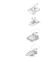
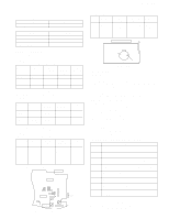
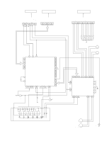
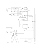
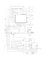
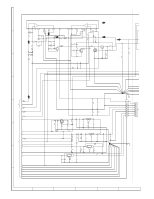
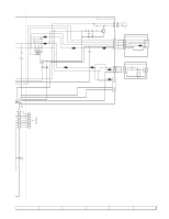
XL-HP500 NOTES ON SCHEMATIC DIAGRAM • Resistor: To differentiate the units of resistors, such symbol as K and M are used: the symbol K means 1000 ohm and the symbol M means 1000 kohm and the resistor without any symbol is ohm-type resistor. Besides, the one with "Fusible" is a fuse type. • Capacitor: To indicate the unit of capacitor, a symbol P is used: this symbol P means pico-farad and the unit of the capacitor without such a symbol is microfarad. As to electrolytic capacitor, the expression "capacitance/withstand voltage" is used. (CH), (TH), (RH), (UJ): Temperature compensation (ML): Mylar type (P.P.): Polypropylene type • Schematic diagram and Wiring Side of P.W.Board for this model are subject to change for improvement without prior notice. • The indicated voltage in each section is the one measured by Digital Multimeter between such a section and the chas- sis with no signal given. 1. In the tuner section, indicates AM indicates FM stereo 2. In the main section, a tape is being played back. 3. In the deck section, a tape is being played back. 4. In the power section, a tape is being played back. 5. In the CD section, the CD is stopped. • Parts marked with " 1 " ( ) are important for maintaining the safety of the set. Be sure to replace these parts with specified ones for maintaining the safety and performance of the set. REF. NO SW4 SW701 SW702 SW703 SW704 SW705 SW706 SW707 SW708 SW712 SW713 SW714 SW715 SW716 SW717 SW718 SW719 DESCRIPTION PICKUP IN POWER ON/STAND-BY CLOCK TIMER/SLEEP TUNING/TIME UP TUNING/TIME DOWN REC/PAUSE REVERSE MODE MEMORY/SET PRESET UP PRESET DOWN PLAY STOP REVERSE PLAY CD TUNER (BAND) TAPE POSITION ON-OFF ON-OFF ON-OFF ON-OFF ON-OFF ON-OFF ON-OFF ON-OFF ON-OFF ON-OFF ON-OFF ON-OFF ON-OFF ON-OFF ON-OFF ON-OFF ON-OFF REF. NO SW720 SW721 SW722 SW723 SW724 SW725 SW726 SW727 SW728 SWB101 SWB102 SWB103 SWB104 SWB105 SWB106 SWB107 SWB108 DESCRIPTION VIDEO/AUX DISC 3 EJECT DISC 2 EJECT DISC 1 EJECT DISC 1 DISC 2 DISC 3 EQUALIZER X-BASS/DEMO CAM 1 CAM 2 CAM 3 CAM 4 CD EJECT CD TRAY CLOSE CD IN CD SET POSITION ON-OFF ON-OFF ON-OFF ON-OFF ON-OFF ON-OFF ON-OFF ON-OFF ON-OFF ON-OFF ON-OFF ON-OFF ON-OFF ON-OFF ON-OFF ON-OFF ON-OFF TYPES OF TRANSISTOR AND LED FRONT VIEW FRONT VIEW EC B (S) (G) (D) (1) (2) (3) KRC102 M KTA1274 Y KRC104 M KTC3199 GR KTA1266 GR KTC3194 Y KTA1271 Y KTC3203 Y KTA1273 Y 2SC1845 F BC E KTC2026 - 12 - FRONT VIEW SLR342VC
-
 1
1 -
2
-
3
-
4
-
5
-
6
-
 7
7 -
 8
8 -
 9
9 -
 10
10 -
 11
11 -
 12
12 -
 13
13 -
 14
14 -
 15
15 -
 16
16 -
 17
17 -
18
-
19
-
20
-
21
-
22
-
23
-
24
-
25
-
26
-
27
-
28
-
29
-
30
-
31
-
32
-
33
-
34
-
35
-
36
-
37
-
38
-
39
-
40
-
41
-
42
-
43
-
44
-
45
-
46
-
47
-
48
-
49
-
50
-
51
-
52
-
53
-
54
-
55
-
56
-
57
-
58
-
59
-
60
 |
 |
