Sharp XL-HP500 Service Manual - Page 9
Adjustment - speaker
 |
View all Sharp XL-HP500 manuals
Add to My Manuals
Save this manual to your list of manuals |
Page 9 highlights
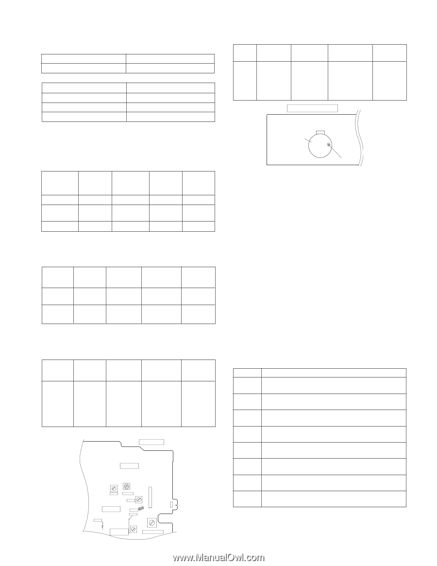
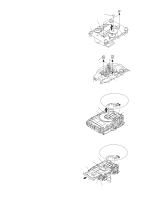
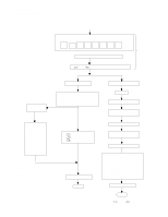
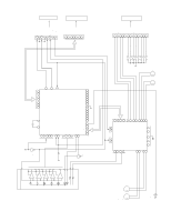
XL-HP500 ADJUSTMENT MECHANISM SECTION • Tape Speed • Driving Force Check Test Tape Torque Meter Specified Value Play: TW-2111 • Torque Check Over 80 g Normal MTT-111 speed Torque Meter Specified Value Play: TW-2111 30 to 80 g.cm Adjusting Point Variable Resistor in motor. Specified Instrument Value Connection 3,000 ± 30 Hz Speaker Terminal (Load resistance: 6 ohms) Fast forward: TW-2231 70 to 180 g.cm TAPE MECHANISM Rewind: TW-2231 70 to 180 g.cm TUNER SECTION fL: Low-range frequency fH: High-range frequency • AM IF/RF Signal generator: 400 Hz, 30%, AM modulated Test Stage Frequency Frequency Setting/ Instrument Display Adjusting Connection Parts AM IF 450 kHz 1,602 kHz T351 *1 AM Band - Coverage 531 kHz (fL): T306 *2 1.1 ± 0.1 V AM Tracking 990 kHz 990 kHz (fL): T303 *1 *1. Input: Antenna Output: TP302 *2. Input: Antenna Output: TP301 • FM RF Signal generator: 1 kHz, 40 kHz dev., FM modulated Test Stage Frequency Frequency Display Setting/ Instrument Adjusting Connection Point FM Band - Coverage 87.50 MHz T301 (fL): *1 1.3 V ± 0.1 V FM RF 98.00 MHz 98.00 MHz L312 *2 (10-30 dB) *1. Input: Antenna Output: TP301 *2. Input: Antenna Output: Speaker terminal • FM IF Signal generator: 10.7 MHz, FM modulated Test Stage Frequency Frequency Display Setting/ Instrument Adjusting Connection Point IF 10.7 MHz 98 MHz T302 *1 (Turn the core of trans- former T302 fully counter- clock wise) Tape Motor Variable Resistor in motor Figure 9-1 CD SECTION • Adjustment Since this CD system incorporates the following automatic adjustment functions, readjustment is not needed when replacing the pickup. Therefore, different PWBs and pickups can be combined freely. Each time a disc is changed, these adjustments are performed automatically. Therefore, playback of each disc can be performed under optimum conditions. Items adjusted automatically (1) Offset adjustment (The offset voltage between the head amplifier output and the VREF reference voltage is compensated inside the IC.) * Focus offset adjustment * Tracking offset adjustment (2) Tracking balance adjustment (3) Gain adjustment (The gain is compensated inside the IC so that the loop gain at the gain crossover frequency will be 0 dB.) * Focus gain adjustment * Tracking gain adjustment CD ERROR CODE DESCRIPTION Error 01 10* 11* Explanation When Pickup set inner position, inner switch cannot detect 'ON' level for 10 secs. CAM error. Can't detect CAM switch when CAM is moving. When it detect CAM operation error during initialize process. *1. Input: Antenna Output: TP301 MAIN PWB-A1 TRAY error. Can't detect TRAY switch when TRAY is 20* moving. When it detect TRAY operation error during initialize 21* process. When it detect invalid TRAY switch during normal IC302 22* operation. R357 IC301 CNP302 T351 TP302 AM IF IC303 T301 FM OSC T302 FM IF L312 FM RF TP301 AM BAND COVERAGE fL T306 T303 AM TRACKING fL FM/AM LOOP ANTENNA Figure 9-2 ADJUSTMENT POINTS When it detect invalid TRAY switch during initialize 23* procecss. When it change to CD function, DSP cannot read 31 initial data. * 'CHECKING' If Error is detected, 'CHECKING' will be displayed instead of 'ER-CD**'. 'ER-CD**' display will only be displayed when error had been detected for the 5th times. - 9 -
-
 1
1 -
2
-
3
-
 4
4 -
 5
5 -
 6
6 -
 7
7 -
 8
8 -
 9
9 -
 10
10 -
 11
11 -
 12
12 -
 13
13 -
 14
14 -
15
-
16
-
17
-
18
-
19
-
20
-
21
-
22
-
23
-
24
-
25
-
26
-
27
-
28
-
29
-
30
-
31
-
32
-
33
-
34
-
35
-
36
-
37
-
38
-
39
-
40
-
41
-
42
-
43
-
44
-
45
-
46
-
47
-
48
-
49
-
50
-
51
-
52
-
53
-
54
-
55
-
56
-
57
-
58
-
59
-
60
 |
 |