Sharp XL-HP500 Service Manual - Page 39
Function Table Of Ic
 |
View all Sharp XL-HP500 manuals
Add to My Manuals
Save this manual to your list of manuals |
Page 39 highlights
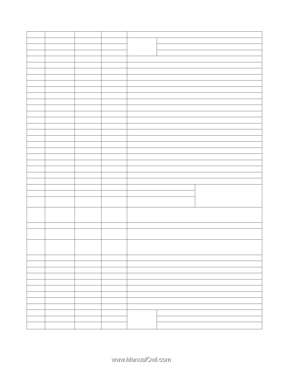
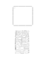
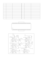
XL-HP500 FUNCTION TABLE OF IC IC1 VHiLC78646E-1: CD Servo (LC78646E) (1/2) Pin No. 1 2 3 4 Terminal Name Input/Output Setting in Reset SLCO Output - SLCIST Input - EFMIN Input - RF Output - Function For slice level control. Control output. Resistor connection terminal for SLCO output current setting. RF signal input terminal. RF signal monitor terminal. 5 RFVDD 6 RFVSS 7 FIN1 8 FIN2 9 TIN1 10 TIN2 11 VREF 12 REF1 13* FE 14 TEC Input - Input Input Input Input Output Input Output Output - - - - - - RFVDD/2 - ZHI - RF power terminal. RF earth terminal. To be connected to 0 V. A+C signal input terminal. B+D signal input terminal. E signal input terminal. F signal input terminal. VREF voltage output terminal. Reference supply setting terminal. FE signal monitor terminal. LPF capacitor connection terminal for TE signal. 15* TE 16* RFMON 17 JITTC 18 ADAVDD 19 ADAVSS 20 TDO 21 FDO Output Output - Input - Output Output ZHI ZHI - - - ADAVDD/2 ADAVDD/2 TE signal monitor terminal. RF internal signal monitor terminal. Capacitor connection terminal for jitter detection. Power terminal for servo A/D, D/A. Earth terminal for serve A/D, D/A. To be connected to 0 V. Output terminal for tracking control. D/A output. Output terminal for focus control. D/A output. 22 SPDO Output ADAVDD/2 Output terminal for spindle control. D/A output. 23 SLDO Output ADAVDD/2 Output terminal for sled control. D/A output. 24* GPDAC Output ADAVDD/2 Servo D/A general-purpose output terminal. 25* CONT4 Input/Output Input Mode General-purpose I/O terminal 4. Controlled by commands from the 26 CONT5 Input/Output Input Mode General-purpose I/O terminal 5. microcomputer. When not used, set them as input terminals and connect 27* SBCK/CONT6 Input/Output Input Mode General-purpose I/O terminal 6 or to 0 V, or set them as output Subcode reading clock input terminal. terminals and leave open. 28 SBCK/FG Input - Subcode reading clock input terminal/FG signal input terminal/external emphasis setting terminal. Terminal functions are set by commands. When not used, connect to 0 V. 29* DEFECT Output L Defect terminal. 30* V/*P Output H Auto switching monitor output terminal for rough servo phase control. "H": rough servo, "L": phase servo. 31* FSEQ 32* MONI1 33* MONI2 34* MONI3 35* MONI4 36* MONI5 37 VSS 38 VDD Output Output Output Output Output Output - Input L Sync signal detection output terminal. The status changes to "H" when the sync signal detected in EFM and the sync signal of internal generation are identified. L Internal signal monitor terminal 1. L Internal signal monitor terminal 2. L Internal signal monitor terminal 3. L Internal signal monitor terminal 4. L Internal signal monitor terminal 5. - Digital system earth terminal. To be connected to 0 V. - Digital system power terminal. 39* DOUT 40 TEST 41 LVDD 42 LCHO 43 LVSS Output Input Input Output - L L - LVDD/2 - Digital OUT output terminal. (EIAJ format) Input terminal for test. To be connected to 0 V. Left channel D/A converter Power supply for Left channel. Left channel output. GND for Left channel. Must be connected to 0 V. In this unit, the terminal with asterisk mark (*) is (open) terminal which is not connected to the outside. - 39 -
-
 1
1 -
2
-
3
-
4
-
5
-
6
-
7
-
8
-
9
-
10
-
11
-
12
-
13
-
14
-
15
-
16
-
17
-
18
-
19
-
20
-
21
-
22
-
23
-
24
-
25
-
26
-
27
-
28
-
29
-
30
-
31
-
32
-
33
-
 34
34 -
 35
35 -
 36
36 -
 37
37 -
 38
38 -
 39
39 -
 40
40 -
 41
41 -
 42
42 -
 43
43 -
 44
44 -
45
-
46
-
47
-
48
-
49
-
50
-
51
-
52
-
53
-
54
-
55
-
56
-
57
-
58
-
59
-
60
 |
 |