Sharp XL-HP500 Service Manual - Page 6
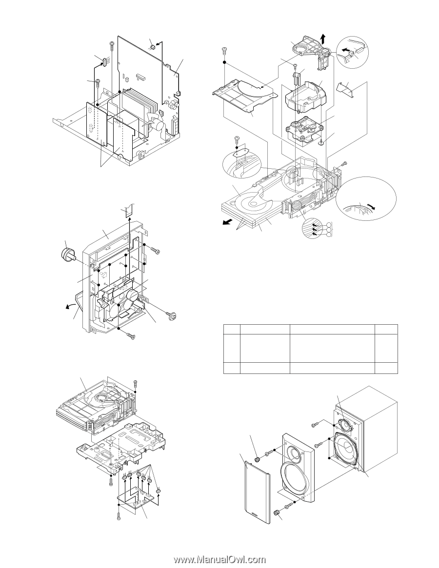
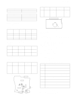
Woofer, Net Frame, A1 x1, Catching Holder, A2 x4, Screw, A3 x4, Screw, A4 x4, Tweeter, Screw, B1 x2 - 3 disc
 |
View all Sharp XL-HP500 manuals
Add to My Manuals
Save this manual to your list of manuals |
Page 6 highlights
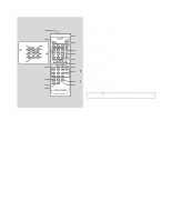
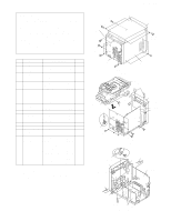
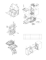
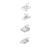
XL-HP500 (F1) x1 ø3x10mm (F2) x1 (F2) x1 Main PWB (G1) x4 ø4x8mm (M2) x2 ø2 x7mm Stabilizer Holder (M4) x1 (M6) x1 ø2.6 x12mm (M7) x1 Push Pawl (M10) x1 (M9) x1 Spring Power PWB Figure 6-1 (H3) x1 Front Panel (H1) x1 Display PWB (H2) x9 ø2.6x10mm Tape Mechanism Open Cassette Holder (K1) x1 ø3x10mm (J1) x4 ø3x10mm Figure 6-2 Headphones PWB CD Changer Mechanism Unit (M1) x2 ø3x10mm (M1) x2 ø3x10mm (L2) x6 (M6) x2 ø2 x6mm Top Board (M3) x1 Disc Tray 1 CD Mechanism (M11) x4 ø2.6 x10mm (M8) x1 ø3 x3mm Turn clockwise the main cam to raise the CD mechanism up to the uppermost position. (M5) x3 Disc Tray 2 Disc Tray 3 1 2 3 Press in turns the arrow parts, starting with the uppermost one, to withdraw the disc trays. Figure 6-4 STEP REMOVAL 1 Woofer 2 Tweeter PROCEDURE FIGURE 1. Net Frame A1) x1 6-5 2. Catching Holder ...... (A2) x4 3. Screw A3) x4 4. Screw A4) x4 1. Screw B1) x2 6-5 Tweeter (A2) x2 (A3) x2 Net Frame ø3x12mm (A1) x1 (B1) x2 ø3x10mm (A4) x4 ø4x12mm Woofer (L1) x3 ø3x10mm Figure 6-3 CD Servo PWB - 6 - (A3) x2 ø3x12mm (A2) x2 Figure 6-5
-
 1
1 -
 2
2 -
 3
3 -
 4
4 -
 5
5 -
 6
6 -
 7
7 -
 8
8 -
 9
9 -
 10
10 -
 11
11 -
 12
12 -
13
-
14
-
15
-
16
-
17
-
18
-
19
-
20
-
21
-
22
-
23
-
24
-
25
-
26
-
27
-
28
-
29
-
30
-
31
-
32
-
33
-
34
-
35
-
36
-
37
-
38
-
39
-
40
-
41
-
42
-
43
-
44
-
45
-
46
-
47
-
48
-
49
-
50
-
51
-
52
-
53
-
54
-
55
-
56
-
57
-
58
-
59
-
60
 |
 |