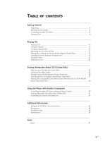
Sony CDPCX455 Primary User Manual - Page 7
Hookups, Connecting the AC power cord, Note on placement of the player, Getting Started - mp3
 |
UPC - 272426017034
View all Sony CDPCX455 manuals
Add to My Manuals
Save this manual to your list of manuals |
Page 7 highlights
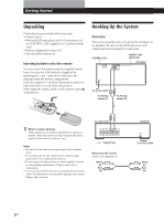
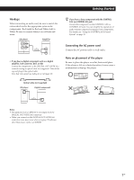
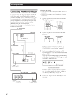
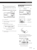
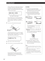
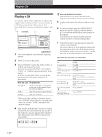
Getting Started Hookups When connecting an audio cord, be sure to match the color-coded cord to the appropriate jacks on the components: Red (right) to Red and White (left) to White. Be sure to connect firmly to avoid hum and noise. CD player L L R R IN 2ND CD OUT ANALOG Amplifier INPUT CD L R • If you have a digital component such as a digital amplifier, D/A converter, DAT, or MD Connect the component via the DIGITAL OUT (OPTICAL) connector using an optical cable (not supplied). Take off the cap and plug in the optical cable. Note that you cannot use fading in or out (page 22). z If you have a Sony component with the CONTROL A1II (or CONTROL A1) jack Connect the component via the CONTROL A1II (or CONTROL A1) jack. You can simplify the operations of audio systems composed of separate Sony components. For details, see "Using the CONTROL A1II Control System" on page 33. Connecting the AC power cord Connect the AC power cord to a wall outlet. Note on placement of the player Be sure to place the player on a flat, horizontal place. If the player is left on a slanted position, it may cause a malfunction or damage the player. Optical cable (not supplied) CD player OPTICAL OUT DIGITAL Digital component DIGITAL INPUT OPTICAL Notes • The playback from an MP3 file is not output from the DIGITAL OUT (OPTICAL) connector. • When you connect via the DIGITAL OUT (OPTICAL) connector, noise may occur when you play CD software other than music, such as a CD-ROM. 7US
-
 1
1 -
 2
2 -
 3
3 -
 4
4 -
 5
5 -
 6
6 -
 7
7 -
 8
8 -
 9
9 -
 10
10 -
 11
11 -
 12
12 -
13
-
14
-
15
-
16
-
17
-
18
-
19
-
20
-
21
-
22
-
23
-
24
-
25
-
26
-
27
-
28
-
29
-
30
-
31
-
32
-
33
-
34
-
35
-
36
-
37
-
38
-
39
-
40
 |
 |
