Sony DVP-CX870D Operating Instructions - Page 10
Receiver (Amplifier) Hookups, may cause the Playback Memory, Bookmark, Disc Explorer - multi disc
 |
View all Sony DVP-CX870D manuals
Add to My Manuals
Save this manual to your list of manuals |
Page 10 highlights
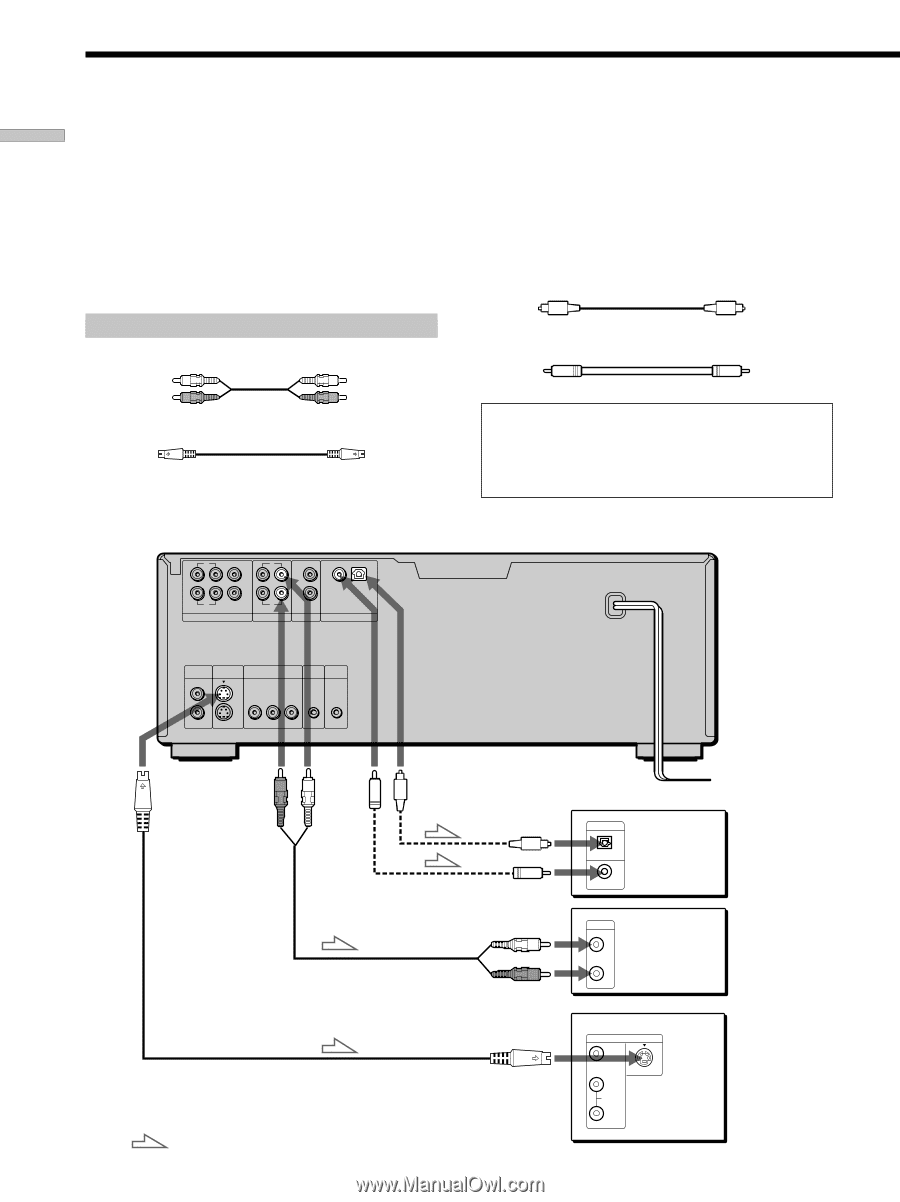
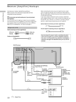
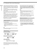
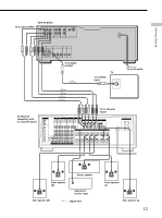
Getting Started Receiver (Amplifier) Hookups Connect your receiver (amplifier) as follows. Refer as well to the instructions supplied with the component to be connected. z You can enjoy surround sounds even if you only connect front speakers You can use 3D sound imaging to create virtual rear speakers from the sound of the front speakers (L, R) without using actual rear speakers (VES: Virtual Enhanced Surround and VIRTUAL SEMI MULTI DIMENSION). For details, see page 47. Required cords Audio connecting cord (not supplied) (1) White (L) Red (R) S video cord (supplied) (1) White (L) Red (R) CD/DVD player L CENTER L L R FRONT REAR WOOFER 5.1 CH OUTPUT R R 2 1 AUDIO OUT AUDIO IN COAXIAL OPTICAL PCM/DTS/ DOLBY DIGITAL DIGITAL OUT When connecting the cords, be sure to match the color-coded cord to the appropriate jacks on the components: Red (right) to Red and White (left) to White. Be sure to make connections firmly to avoid hum and noise. If you have a digital component such as a receiver (amplifier) with a digital connector, DAT or MD, connect the component via the DIGITAL OUT OPTICAL or COAXIAL connector using an optical or coaxial digital connecting cord (not supplied). Optical digital connecting cord (not supplied) (1) Coaxial digital connecting cord (not supplied) (1) Do not connect the power cord to a switched AC outlet such as the AC outlet on a receiver (amplifier). Doing so may cause the Playback Memory, Bookmark, Disc Explorer and menu settings to be cancelled when you turn off the receiver. VIDEO S VIDEO OUTPUT OUTPUT 1 1 2 2 COMPONENT VIDEO OUT MEGA CONTROL S-LINK Y PB PR CONTROL S IN To AUDIO OUT (R, L) To S VIDEO OUTPUT 10 : Signal flow To DIGITAL OUT (COAXIAL) To DIGITAL OUT (OPTICAL) Take off the cap. To optical digital input or To coaxial digital input or To audio input DIGITAL IN OPTICAL COAXIAL CD L R To an AC outlet Receiver (Amplifier) with a digital connector, MD deck, DAT deck, etc. Receiver (Amplifier) TV INPUT VIDEO To S VIDEO input L AUDIO S VIDEO R
-
 1
1 -
2
-
3
-
4
-
 5
5 -
 6
6 -
 7
7 -
 8
8 -
 9
9 -
 10
10 -
 11
11 -
 12
12 -
 13
13 -
 14
14 -
 15
15 -
16
-
17
-
18
-
19
-
20
-
21
-
22
-
23
-
24
-
25
-
26
-
27
-
28
-
29
-
30
-
31
-
32
-
33
-
34
-
35
-
36
-
37
-
38
-
39
-
40
-
41
-
42
-
43
-
44
-
45
-
46
-
47
-
48
-
49
-
50
-
51
-
52
-
53
-
54
-
55
-
56
-
57
-
58
-
59
-
60
-
61
-
62
-
63
-
64
-
65
-
66
-
67
-
68
-
69
-
70
-
71
-
72
-
73
-
74
-
75
-
76
-
77
-
78
-
79
-
80
-
81
-
82
-
83
-
84
-
85
-
86
-
87
-
88
-
89
-
90
-
91
-
92
-
93
-
94
-
95
-
96
 |
 |