Sony HCD-NEZ30 Service Manual - Page 14
Hcd-nez30, Electrical, Adjustments
 |
View all Sony HCD-NEZ30 manuals
Add to My Manuals
Save this manual to your list of manuals |
Page 14 highlights
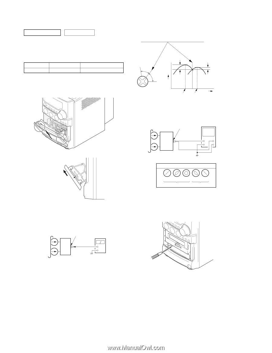
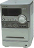
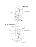
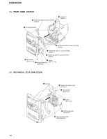
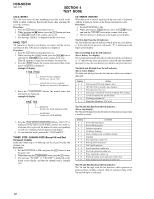
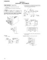
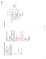
HCD-NEZ30 SECTION 6 ELECTRICAL ADJUSTMENTS DECK SECTION 0 dB=0.775 V 1. Demagnetize the record/playback head with a head demagnetizer. 2. Do not use a magnetized screwdriver for the adjustments. • Test Tape Tape P-4-A063 Signal 6.3 kHz, -10 dB Used for Azimuth Adjustment RECORD/PLAYBACK HEAD AZIMUTH ADJUSTMENT Note: Remove the cassette lid assy before this adjustment. 2. Turn the adjustment screw and check output peaks. If the peaks do not match for L-CH and R-CH, turn the adjustment screw so that outputs match within 1dB of peak. L-CH peak within 1dB Output level Screw position R-CH peak L-CH R-CH peak peak within 1dB Screw position 3. Mode: Playback test tape HEAD PHONE board P-4-A063 (6.3 kHz, -10 dB) PHONES jack (J500) oscilloscope VH set Procedure: 1. Mode: Playback test tape P-4-A063 (6.3 kHz, -10 dB) HEAD PHONE board PHONES jack (J500) level meter set + - waveform of oscilloscope in phase 45° 90° 135° 180° good wrong 4. After the adjustments, apply suitable locking compound to the pats adjusted. Adjustment Location: Record/Playback/Erase Head 14
-
 1
1 -
2
-
3
-
4
-
5
-
6
-
7
-
8
-
 9
9 -
 10
10 -
 11
11 -
 12
12 -
 13
13 -
 14
14 -
 15
15 -
 16
16 -
 17
17 -
 18
18 -
 19
19 -
20
-
21
-
22
-
23
-
24
-
25
-
26
-
27
-
28
-
29
-
30
-
31
-
32
-
33
-
34
-
35
-
36
-
37
-
38
-
39
-
40
-
41
-
42
-
43
-
44
-
45
-
46
-
47
-
48
-
49
-
50
-
51
 |
 |