Sony HCD-NEZ30 Service Manual - Page 35
Sony HCD-NEZ30 - Cd Deck Receiver Component Manual
 |
View all Sony HCD-NEZ30 manuals
Add to My Manuals
Save this manual to your list of manuals |
Page 35 highlights
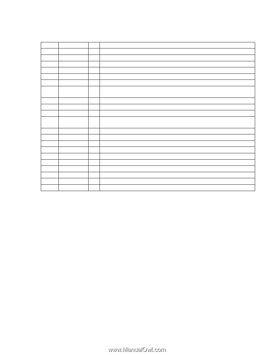
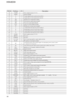
HCD-NEZ30 Pin No. 46 47 48 49 50 51 to 53 Pin Name O-POWER I-SUFFIX I-RE-VOL I-MP3-REQ I-MP3-ACK MD2 to MD0 54 RESET 55 O-TU-CE 56 O-TU-CLK 57 O-TU-DI I/O Description O Power relay drive signal output terminal "H": on I Model destination setting terminal I Dial pulse input of the rotary encoder (for VOLUME control) I MP3 data request signal input from the CD DSP I MP3 acknowledge signal input from the CD DSP - Not used I Reset signal input from the reset switch "L": reset For several hundreds msec. after the power supply rises, "L" is input, then it changes to "H" O Chip enable signal output to the tuner (FM/AM) O serial data transfer clock signal output to the tuner (FM/AM) O Serial data output to the tuner (FM/AM) 58 VLCD - Terminal for doubler circuit capacitor connection to develop liquid crystal display drive voltage 59 to 62 COM0 to COM3 O Common drive signal output to the liquid crystal display 63, 64 SEG0, SEG1 O Segment drive signal output to the liquid crystal display 65 VCC - Power supply terminal (+3.2V) 66 GND - Ground terminal 67 to 89 SEG2 to SEG24 O Segment drive signal output to the liquid crystal display 90 VCC - Power supply terminal (+3.2V) 91 VSS - Ground terminal 92 XI I Main system clock input terminal (4.19 MHz) 93 XO O Main system clock output terminal (4.19 MHz) 94 to 100 SEG25 to SEG31 O Segment drive signal output to the liquid crystal display 35
-
 1
1 -
2
-
3
-
4
-
5
-
6
-
7
-
8
-
9
-
10
-
11
-
12
-
13
-
14
-
15
-
16
-
17
-
18
-
19
-
20
-
21
-
22
-
23
-
24
-
25
-
26
-
27
-
28
-
29
-
 30
30 -
 31
31 -
 32
32 -
 33
33 -
 34
34 -
 35
35 -
 36
36 -
 37
37 -
 38
38 -
 39
39 -
 40
40 -
41
-
42
-
43
-
44
-
45
-
46
-
47
-
48
-
49
-
50
-
51
 |
 |