Sony KDF-60XBR950 Operating Instructions - Page 23
Installing and Connecting the LCD Projection TV, VHF/UHF, CABLE, i.LINK, S VIDEO, Front and rear
 |
UPC - 027242633186
View all Sony KDF-60XBR950 manuals
Add to My Manuals
Save this manual to your list of manuals |
Page 23 highlights
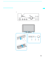
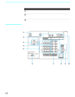
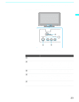
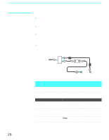
Installing and Connecting the LCD Projection TV Front Panel of LCD projection TV Installing and Connecting the LCD Projection TV S VIDEO VIDEO 2 IN VIDEO L-AUDIO-R (MONO) MENU Front panel connectors are in the control panel cover. To open and close the cover, refer to page 21. Connection 1 VHF/UHF 2 CABLE 3 i.LINK 4 S VIDEO (Front and rear) 5 VIDEO/ (L/R) AUDIO (Front and rear) Description Connects to your VHF/UHF antenna or cable box output jack. Connects to your cable signal. This CABLE input jack, in conjunction with the VHF/UHF input jack, lets you set up your LCD projection TV to switch between scrambled channels (coming through a cable box) and unscrambled cable channels. For details, see page 28. Connects to i.LINK-compatible devices. These terminals are not intended for connection with personal computers. Connects to the S VIDEO OUT jack of your VCR or other S VIDEO-equipped video component. Provides better picture quality than the VHF/UHF jacks or the Video IN jack. Connects to the audio and video OUT jacks on your VCR or other video component. A fourth video input (VIDEO 2) is located on the front panel of the LCD projection TV. (Continued) 23
-
 1
1 -
2
-
3
-
4
-
5
-
6
-
7
-
8
-
9
-
10
-
11
-
12
-
13
-
14
-
15
-
16
-
17
-
 18
18 -
 19
19 -
 20
20 -
 21
21 -
 22
22 -
 23
23 -
 24
24 -
 25
25 -
 26
26 -
 27
27 -
 28
28 -
29
-
30
-
31
-
32
-
33
-
34
-
35
-
36
-
37
-
38
-
39
-
40
-
41
-
42
-
43
-
44
-
45
-
46
-
47
-
48
-
49
-
50
-
51
-
52
-
53
-
54
-
55
-
56
-
57
-
58
-
59
-
60
-
61
-
62
-
63
-
64
-
65
-
66
-
67
-
68
-
69
-
70
-
71
-
72
-
73
-
74
-
75
-
76
-
77
-
78
-
79
-
80
-
81
-
82
-
83
-
84
-
85
-
86
-
87
-
88
-
89
-
90
-
91
-
92
-
93
-
94
-
95
-
96
-
97
-
98
-
99
-
100
-
101
-
102
-
103
-
104
-
105
-
106
-
107
-
108
-
109
-
110
-
111
-
112
-
113
-
114
-
115
-
116
-
117
-
118
-
119
-
120
 |
 |
