Sony KDL-46V25L1 Instructions - Page 7
Adjust the angle of the arms., Change the position of the, Mounting Hook Unit support, shafts. - settings
 |
View all Sony KDL-46V25L1 manuals
Add to My Manuals
Save this manual to your list of manuals |
Page 7 highlights
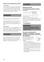
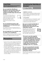
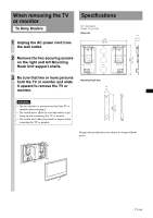
2 Adjust the angle of the arms. When installing the TV or monitor perpendicularly (0 degrees), adjustment of the arm angle (procedures 1 and 2 below) is not necessary. Make sure that each arm base is screwed in securely. 1 Remove the screws from the top and bottom centre of the both arm bases. Then choose the notch corresponding to the desired angle (5, 10, 15 or 20 degrees) and fit each arm base to them. If you are installing the KLV-40U100M, do not choose the notch for 20 degrees. 2 Firmly secure each arm base using the screws removed in the above procedure 1. 3 Change the position of the Mounting Hook Unit support shafts. 1 Remove the screws securing the both left and right Mounting Hook Unit support shafts, and then move the Mounting Hook Unit support shafts to the inner position. Make sure the marks on the both Mounting Hook Unit support shafts align with the F marks on the plate unit. 2 Secure the Mounting Hook Unit support shafts using the screws from procedure 1. Notes • Be sure to adjust the angles of the right and left arms to the same angle. • Be careful not to pinch your fingers when adjusting the angle of the arms. • When using an electric screwdriver, set the torque setting to approximately 2 N·m {20 Kgf·cm}. • Make sure that the two arm bases are screwed in securely. Notes on the adjustment angles • When installing TV or monitor models other than those specified on page 2 (depending on the model's size and dimensions, etc.), the adjustment angles listed (0, 5, 10, 15, 20 degrees) for the arms may be limited. • For the available adjustment angles of the arms when installing TV or monitor models other than those specified on page 2, refer to the operating instructions or the leaflet ("Installing the WallMount Bracket") supplied with the TV or monitor. • 0 degrees: Leave the white screws tightened as they are. • Other than 0 degrees: Remove the white screws. Mounting Hook Unit support shaft Notes • When using an electric screwdriver, set the torque setting to approximately 2 N·m {20 Kgf·cm}. • Make sure that the two Mounting Hook Unit support shafts are screwed in securely. Arm base 12 7 (GB)
-
 1
1 -
 2
2 -
 3
3 -
 4
4 -
 5
5 -
 6
6 -
 7
7 -
 8
8 -
 9
9 -
 10
10 -
 11
11 -
 12
12 -
13
-
14
-
15
-
16
-
17
-
18
-
19
-
20
-
21
-
22
-
23
-
24
-
25
-
26
-
27
-
28
-
29
-
30
-
31
-
32
-
33
-
34
-
35
-
36
-
37
-
38
-
39
-
40
-
41
-
42
-
43
-
44
-
45
-
46
-
47
-
48
-
49
-
50
-
51
-
52
-
53
-
54
-
55
-
56
-
57
-
58
-
59
-
60
-
61
-
62
-
63
-
64
-
65
-
66
-
67
-
68
-
69
-
70
-
71
-
72
-
73
-
74
-
75
-
76
-
77
-
78
-
79
-
80
-
81
-
82
-
83
-
84
-
85
-
86
-
87
-
88
-
89
-
90
-
91
-
92
-
93
-
94
-
95
-
96
-
97
-
98
-
99
-
100
-
101
-
102
-
103
-
104
-
105
-
106
-
107
-
108
-
109
-
110
-
111
-
112
 |
 |
