Sony KV-1354R Primary User Manual - Page 13
Ei5Q-u
 |
View all Sony KV-1354R manuals
Add to My Manuals
Save this manual to your list of manuals |
Page 13 highlights
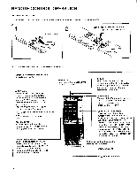
PRESETTING PROCEDURE Presetting compartment 0 0 0 Remove the lid and expose the switches and buttons. CHANNEL scan buttons 1 Depre-ss the POWER switch. 2 Set the CHANNEL SET switch to ON. Hit button Turn on the equipment connected to the Hit. (If it is a VCR, play back a prerecorded tape.) The selected program position number should blink with the picture of the presently set channel. If the picture turns black or into snow, set BAND SELECT switch to either of the remaining 2 positions so that the number blinks clearly. 3 Select the channel position to be preset with ' the CHANNEL scan buttons. .. i • --)4- The selected position number _ "L should blink. - If the number cannot be ,...,C_C-_________::D identified, reset BAND SELECT switch as in step 2. Press the Hit button. The Hit indication should blink. 8k AS #,,, .S:a r e 4 Set the BAND SELECT switch to one of these three positions: VHF channels 2 through 6...set to VL VHF channels 7 through 13...set to VH UHF channels 14 to 83...set to U Band VL will be selected regardless of the BAND SELECT switch setting. Y. vLH-Ei5Q-u • V Selected band is underlined. . I -14 / 1-FI Li \ 1 - LH_it_. 5 Keep the + or - TUNING button pressed until... the clear picture of the desired station is obtained. the signals fed from the Hit connector are properly tuned in. for lower-numbered channels TUNING _ + CI • for higher-numbered channels The length of the bar provides a visual indication of the approximate location you are tuned to within the selected band. Lower-numbered channels - Higher-numbered channels Band VL Band VH Band U 2 6 7 13 14 83 The RESPONSE lamp lights steadily when the highest- or the lowest-numbered channel within the present band is tuned in. Repeat steps 3 through 5 for all the channel positions to be Preset. 6 Set the CHANNEL SET switch to OFF. 13
-
 1
1 -
2
-
3
-
4
-
5
-
6
-
7
-
 8
8 -
 9
9 -
 10
10 -
 11
11 -
 12
12 -
 13
13 -
 14
14 -
 15
15 -
 16
16 -
 17
17
 |
 |
