Sony MDS-JE470 Service Manual - Page 6
Jig For Checking Bd Board Waveform, Gnd : Ground
 |
View all Sony MDS-JE470 manuals
Add to My Manuals
Save this manual to your list of manuals |
Page 6 highlights
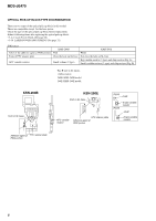
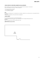
MDS-JE470 JIG FOR CHECKING BD BOARD WAVEFORM The special jig (J-2501-196-A) is useful for checking the waveform of the BD board. The names of terminals and the checking items to be performed are shown as follows. GND : Ground I+3V : For measuring IOP (Check the deterioration of the optical pick-up laser) IOP : For measuring IOP (Check the deterioration of the optical pick-up laser) TE : TRK error signal (Traverse adjustment) VC : Reference level for checking the signal RF : RF signal (Check jitter) FE : Focus error signal CN105 IOP TE VC I+3V GND FE RF 6 I+3V IOP GND TE FE VC RF 1 I+3V Iop GND TE FE VC RF 7 for MDM-7A
-
 1
1 -
 2
2 -
 3
3 -
 4
4 -
 5
5 -
 6
6 -
 7
7 -
 8
8 -
 9
9 -
 10
10 -
 11
11 -
 12
12 -
13
-
14
-
15
-
16
-
17
-
18
-
19
-
20
-
21
-
22
-
23
-
24
-
25
-
26
-
27
-
28
-
29
-
30
-
31
-
32
-
33
-
34
-
35
-
36
-
37
-
38
-
39
-
40
-
41
-
42
-
43
-
44
-
45
-
46
-
47
-
48
-
49
-
50
-
51
-
52
-
53
-
54
-
55
-
56
-
57
-
58
-
59
-
60
-
61
-
62
-
63
-
64
-
65
-
66
-
67
-
68
-
69
-
70
 |
 |

6
MDS-JE470
JIG FOR CHECKING BD BOARD WAVEFORM
The special jig (J-2501-196-A) is useful for checking the waveform of the BD board. The names of terminals and the checking items to be
performed are shown as follows.
GND : Ground
I+3V
: For measuring IOP (Check the deterioration of the optical pick-up laser)
IOP
: For measuring IOP (Check the deterioration of the optical pick-up laser)
TE
:
TRK error signal (Traverse adjustment)
VC
:
Reference level for checking the signal
RF
: RF signal (Check jitter)
FE
: Focus error signal
I+3V
Iop
GND
TE
FE
VC
RF
I+3V
IOP
GND
TE
FE
VC
RF
1
7
for
MDM-7A
I+3V
CN105
IOP
TE
VC
GND
FE
RF