Sony NWZA816P Service Manual - Page 9
Board, Switch, Flexible Pwb, Installing - black
 |
UPC - 027242721456
View all Sony NWZA816P manuals
Add to My Manuals
Save this manual to your list of manuals |
Page 9 highlights
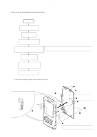
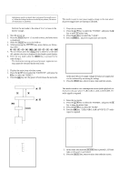
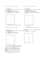
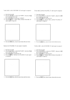
NW-A805/A806/A808/NWZ-A815/A816/A818 Ver. 1.4 3-5. NAND BOARD, SVX SWITCH FLEXIBLE (PWB ASSY) 9 sheet (NAND) 3 two screws (M1.4) 5 Lift up the NAND board. 4 Turn up the LCD flexible board. 2 Lift up the SVX swtch flexible (PWB assy). 1 two claws - rear view - (NW-A805/A806/ NWZ-A815/A816 only) q; spacer (NAND) qa NAND board 6 Remove three solders. 7 insulating sheet 8 SVX swtch flexible (PWB assy) 3-6. NOTE WHEN INSTALLING THE SVX SWITCH FLEXIBLE (PWB ASSY) Note: Follow the assembly procedure in the numerical order given. Note: Route the lead wires as shown in the figure, and solder them at the angle shown in the figure. SVX swtch flexible (PWB assy) Note: The soldering height should be less than 0.8 mm. lead wire (red) lead wire (gray) About 45° lead wires front cabinet assy 2 Holding the bent part, rotate the SVX swtch flexible (PWB assy) by 3 or 4 turns in the arrow direction, and twist to bind the lead wires. 1 Bend the switch flexible board. claw LCD holder claw About 45° lead wire (black) NAND board - rear view - 3 Holding the bent part, push in the SVX swtch flexible (PWB assy) until it gets stuck by two claws of the front cabinet assy. 4 Push the lead wires completely into a space between front cabinet assy and LCD holder. 9
-
 1
1 -
2
-
3
-
 4
4 -
 5
5 -
 6
6 -
 7
7 -
 8
8 -
 9
9 -
 10
10 -
 11
11 -
 12
12 -
 13
13 -
 14
14 -
15
-
16
-
17
-
18
-
19
-
20
-
21
-
22
-
23
-
24
-
25
-
26
-
27
-
28
-
29
-
30
-
31
-
32
-
33
-
34
-
35
-
36
-
37
-
38
-
39
-
40
-
41
-
42
-
43
-
44
-
45
-
46
-
47
-
48
-
49
-
50
-
51
-
52
 |
 |
