Sony PDW700 User Manual (PDW-700 / PDW-F800 Operation Manual for Firmware Vers - Page 15
Locations and Functions of Parts and Controls, Power supply
 |
View all Sony PDW700 manuals
Add to My Manuals
Save this manual to your list of manuals |
Page 15 highlights
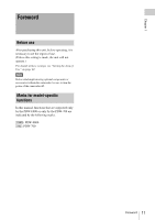
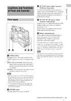
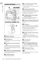
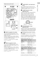
Chapter 1 Overview Locations and Functions of Parts and Controls Power supply 12 3 45 a LIGHT switch Determines how a video light connected to the LIGHT connector (see page 16) is turned on and off. AUTO: When the POWER switch of the video light is in the on position, the video light is turned on automatically while the camcorder is recording. MANUAL: You can turn the video light on or off manually, using its own switch. Notes • When this switch is set to AUTO, at the beginning of the recording, the picture is recorded even though the lighting may fluctuate until the video light comes on. If the beginning of the recording is important, you should set this switch to MANUAL. • To ensure proper operation of the video light, Sony recommends the use of the BP-GL95/L80S Battery Pack with the camcorder. b POWER switch Turns the main power supply on and off. c DC IN (DC power input) connector (XLR type, 4-pin, male) To operate the camcorder from an AC power supply, connect an optional DC power cord to this terminal and then connect the cord to the DC output terminal of the BC-L70, BC-M150, or another battery charger. d DC OUT 12V (DC power output) connector (4-pin, female) Supplies power for a WRR-860A/861/862 UHF Synthesized Diversity Tuner (not supplied) (maximum 0.5 A). Do not connect any equipment other than the UHF synthesized diversity tuner. e Battery attachment shoe Attach a BP-GL95/GL65/L60S/L80S Battery Pack. Alternatively, you can attach an ACDN2B/DN10 AC Adaptor to operate the camcorder on AC power supply. For details about how to attach the battery or AC adaptor, see "Preparing a Power Supply" on page 37. For information about attaching a synthesized tuner, see "Attaching a UHF portable tuner (for a UHF wireless microphone system)" on page 48. Note For your safety, and to ensure proper operation of the camcorder, Sony recommends the use of the following battery packs: BP-GL95, BP-GL65, BP-L60S, and BPL80S. Locations and Functions of Parts and Controls 15
-
 1
1 -
2
-
3
-
4
-
5
-
6
-
7
-
8
-
9
-
 10
10 -
 11
11 -
 12
12 -
 13
13 -
 14
14 -
 15
15 -
 16
16 -
 17
17 -
 18
18 -
 19
19 -
 20
20 -
21
-
22
-
23
-
24
-
25
-
26
-
27
-
28
-
29
-
30
-
31
-
32
-
33
-
34
-
35
-
36
-
37
-
38
-
39
-
40
-
41
-
42
-
43
-
44
-
45
-
46
-
47
-
48
-
49
-
50
-
51
-
52
-
53
-
54
-
55
-
56
-
57
-
58
-
59
-
60
-
61
-
62
-
63
-
64
-
65
-
66
-
67
-
68
-
69
-
70
-
71
-
72
-
73
-
74
-
75
-
76
-
77
-
78
-
79
-
80
-
81
-
82
-
83
-
84
-
85
-
86
-
87
-
88
-
89
-
90
-
91
-
92
-
93
-
94
-
95
-
96
-
97
-
98
-
99
-
100
-
101
-
102
-
103
-
104
-
105
-
106
-
107
-
108
-
109
-
110
-
111
-
112
-
113
-
114
-
115
-
116
-
117
-
118
-
119
-
120
-
121
-
122
-
123
-
124
-
125
-
126
-
127
-
128
-
129
-
130
-
131
-
132
-
133
-
134
-
135
-
136
-
137
-
138
-
139
-
140
-
141
-
142
-
143
-
144
-
145
-
146
-
147
-
148
-
149
-
150
-
151
-
152
-
153
-
154
-
155
-
156
-
157
-
158
-
159
-
160
-
161
-
162
-
163
-
164
-
165
-
166
-
167
-
168
-
169
-
170
-
171
-
172
-
173
-
174
-
175
-
176
-
177
-
178
-
179
-
180
-
181
-
182
-
183
-
184
-
185
-
186
-
187
-
188
-
189
-
190
-
191
-
192
-
193
-
194
-
195
-
196
-
197
-
198
-
199
-
200
-
201
-
202
-
203
-
204
-
205
-
206
-
207
-
208
-
209
-
210
-
211
-
212
-
213
-
214
-
215
-
216
-
217
-
218
-
219
-
220
-
221
-
222
-
223
-
224
-
225
-
226
-
227
-
228
-
229
-
230
-
231
-
232
-
233
-
234
-
235
-
236
-
237
-
238
-
239
-
240
-
241
-
242
-
243
-
244
-
245
-
246
-
247
-
248
-
249
-
250
-
251
-
252
-
253
-
254
-
255
-
256
-
257
-
258
-
259
-
260
-
261
-
262
-
263
-
264
-
265
-
266
-
267
-
268
-
269
-
270
-
271
-
272
-
273
-
274
-
275
-
276
-
277
 |
 |