Sony PDW700 User Manual (PDW-700 / PDW-F800 Operation Manual for Firmware Vers - Page 29
TEST OUT connector BNC type, TC OUT timecode output connector
 |
View all Sony PDW700 manuals
Add to My Manuals
Save this manual to your list of manuals |
Page 29 highlights
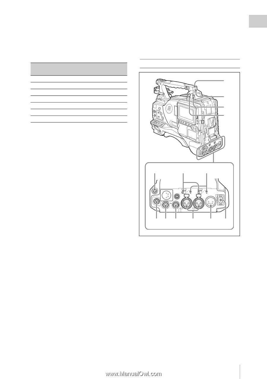
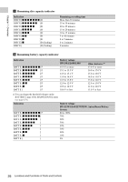
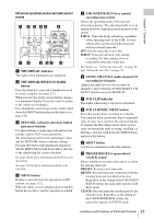
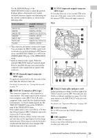
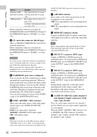
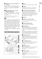
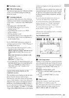
Chapter 1 Overview Use the GENLOCK page of the MAINTENANCE menu to adjust the genlock H-phase (phase of horizontal sync signal). Available reference signals vary depending on the current system frequency as shown in the following table. System frequency 1080/59.94i 1080/50i 1080/29.97P 1080/25P 1080/23.98P 720/59.94P 720/50P Available reference signals 1080/59.94i, 525/59.94i 1080/50i, 625/50i 1080/59.94i, 525/59.94i 1080/50i, 625/50i 1080/23.98PsF 1080/59.94i, 525/59.94i 1080/50i, 625/50i • This connector also inputs a return video signal. You can display the HD-Y (1080i) signal in the viewfinder screen while holding the RET button down with RETURN VIDEO set to ON on the ASSIGNABLE SW page of the OPERATION menu. • Input an external video signal. When the optional CBK-SC02 Analog Composite Input Board is installed, the unit can record analog composite video signals that are input to this connector. e TC IN (timecode input) connector (BNC type) To apply an external lock to the timecode of this unit, input the reference timecode. For details of timecode, see "Setting the timecode" on page 74. f TEST OUT connector (BNC type) This connector outputs the video signal for a video monitor. The output signal can be selected from composite video, HD-Y, R, G, B, and a composite video signal like that displayed in the LCD monitor. To switch output signals, use the TEST OUT SELECT item on the OUTPUT 1 page of the OPERATION menu. If the output signal is set to one of R, G, or B, then this setting changes to HD-Y when the camcorder is powered off and on again. Depending on menu settings, menus, timecode, and shot data can be superimposed on the image on the monitor. This connector can also be used to synchronize the timecode of an external VTR with the timecode of the camcorder. g TC OUT (timecode output) connector (BNC type) To lock the timecode of an external VTR to the timecode of this unit, connect this connector to the external VTR's timecode input connector. Rear 1 2 3 4 5 6 7 AES/EBU AUDIO IN AES/EBU LINE MIC LINE MIC 48V 48V DC OUT OFF 12V OFF AUDIO OUT DC 0.5A IN SUPER SDI OUT SDI OUT CH1 1/2 CH2 3/4 8 9 0 qa qs qd a TALLY (back tally) indicator (red) Lights up during recording. It will not light if the TALLY switch is set to OFF. This indicator also flashes to indicate warnings (see page 22) in the same manner as the REC/TALLY indicator in the viewfinder. For details, see "Operation Warnings" on page 247. b TALLY switch Set to ON to activate the TALLY indicator function. c USB connector This is a USB 2.0 connector. Connect one of the following devices, depending on what you want to do. Locations and Functions of Parts and Controls 29
-
 1
1 -
2
-
3
-
4
-
5
-
6
-
7
-
8
-
9
-
10
-
11
-
12
-
13
-
14
-
15
-
16
-
17
-
18
-
19
-
20
-
21
-
22
-
23
-
 24
24 -
 25
25 -
 26
26 -
 27
27 -
 28
28 -
 29
29 -
 30
30 -
 31
31 -
 32
32 -
 33
33 -
 34
34 -
35
-
36
-
37
-
38
-
39
-
40
-
41
-
42
-
43
-
44
-
45
-
46
-
47
-
48
-
49
-
50
-
51
-
52
-
53
-
54
-
55
-
56
-
57
-
58
-
59
-
60
-
61
-
62
-
63
-
64
-
65
-
66
-
67
-
68
-
69
-
70
-
71
-
72
-
73
-
74
-
75
-
76
-
77
-
78
-
79
-
80
-
81
-
82
-
83
-
84
-
85
-
86
-
87
-
88
-
89
-
90
-
91
-
92
-
93
-
94
-
95
-
96
-
97
-
98
-
99
-
100
-
101
-
102
-
103
-
104
-
105
-
106
-
107
-
108
-
109
-
110
-
111
-
112
-
113
-
114
-
115
-
116
-
117
-
118
-
119
-
120
-
121
-
122
-
123
-
124
-
125
-
126
-
127
-
128
-
129
-
130
-
131
-
132
-
133
-
134
-
135
-
136
-
137
-
138
-
139
-
140
-
141
-
142
-
143
-
144
-
145
-
146
-
147
-
148
-
149
-
150
-
151
-
152
-
153
-
154
-
155
-
156
-
157
-
158
-
159
-
160
-
161
-
162
-
163
-
164
-
165
-
166
-
167
-
168
-
169
-
170
-
171
-
172
-
173
-
174
-
175
-
176
-
177
-
178
-
179
-
180
-
181
-
182
-
183
-
184
-
185
-
186
-
187
-
188
-
189
-
190
-
191
-
192
-
193
-
194
-
195
-
196
-
197
-
198
-
199
-
200
-
201
-
202
-
203
-
204
-
205
-
206
-
207
-
208
-
209
-
210
-
211
-
212
-
213
-
214
-
215
-
216
-
217
-
218
-
219
-
220
-
221
-
222
-
223
-
224
-
225
-
226
-
227
-
228
-
229
-
230
-
231
-
232
-
233
-
234
-
235
-
236
-
237
-
238
-
239
-
240
-
241
-
242
-
243
-
244
-
245
-
246
-
247
-
248
-
249
-
250
-
251
-
252
-
253
-
254
-
255
-
256
-
257
-
258
-
259
-
260
-
261
-
262
-
263
-
264
-
265
-
266
-
267
-
268
-
269
-
270
-
271
-
272
-
273
-
274
-
275
-
276
-
277
 |
 |