Sony PDW700 User Manual (PDW-700 / PDW-F800 Operation Manual for Firmware Vers - Page 223
Select the desired function, and press, the MENU knob., Functions to be assigned to the ASSIGN 2
 |
View all Sony PDW700 manuals
Add to My Manuals
Save this manual to your list of manuals |
Page 223 highlights
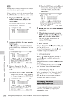
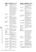
ASSIGN 1/3/4 switches allow you to display or not to display all markers. b) This function cannot be assigned to the RET button on the lens. c) Even if the RETURN VIDEO item is set to OFF on the ASSIGNABLE SW page of the OPERATION menu, you can use this switch to display the image of the return video signal on the viewfinder. d) Only the Assign 3 SEL and Assign 4 SEL screens appear. e) Video momentarily becomes black and audio is momentarily muted when the digital extender is switched on and off. f) This does not appear if nothing is assigned in the Assign menu. Functions to be assigned to the ASSIGN 2 (slide-type) switch Function Content OFF Assigns no function. FRONT MIC Assigns the function that switches between stereo and monaural when a stereo microphone is connected. PICTURE Assigns execution of CACHE recording in picture cache mode. SUPER Assigns a mixing switch (VFDISP&M function that selects mixing or ENU) no mixing of superimposed viewfinder and menu text data into the video signals output from the SDI OUT 2 or TEST OUT connector, when SDI OUT 2 SUPER or TEST OUT SUPER on the OUTPUT 1 page of the OPERATION menu are set to ON. MARKER Assigns the function that displays or hides all markers. a) REC VIDEO Switches the recording target SOURCE video between the video shot by the camera and the video input from an external device (VBS or SD-SDI/HD-SDI). b) ZEBRA Assigns the zebra pattern display function. FREEZE MIX Assigns the function that mixes a still picture (monochrome) and camera video (color) (effective for framing shots). Function Content DIGITAL Assigns the function that EXTENDER c) electronically magnifies the central part of the picture. (All video output is magnified, including recorded video.) CLIP CONT Assigns the function that REC turns the Clip Continuous Rec function on and off. UA01 to Assigns the items assigned in UA10 d) the ASSIGN SEL menu. a) Even when the MARKER item is set to OFF on the MARKER page of the USER menu, the ASSIGN 2 switch allows you to display or not to display all markers. b) The optional CBK-SC02 Analog Composite Input Board is required for VBS signal input. The optional CBK-HD01 HD/SD SDI Input Board is required for SD-SDI/HD-SDI signal input. c) Video momentarily becomes black and audio is momentarily muted when the digital extender is switched on and off. d) This does not appear if nothing is assigned in the Assign menu. Note For functions that are assigned to the ASSIGN 2 (slide-type) switch, you cannot change those settings using other menus. The function assigned to the ASSIGN 2 switch takes precedence over the menu setting. 3 Select the desired function, and press the MENU knob. The function is assigned, and the ASSIGNABLE SW page appears again. Operation of the ASSIGN 1/2/3/4 switches when UA01 to UA10 are assigned When an on/off switchable function (or menu item) is assigned to one of the ASSIGN 1/2/3/4 switches, each time the switch is pressed toggles the function on or off. When another type of menu item is assigned, pressing the switch displays the item and its setting value on the viewfinder screen. You can then change the setting by pressing and turning the MENU knob. The viewfinder screen display disappears approximately three seconds after the last operation. Chapter 6 Menu Displays and Detailed Settings Adjustments and Settings from Menus 223
-
 1
1 -
2
-
3
-
4
-
5
-
6
-
7
-
8
-
9
-
10
-
11
-
12
-
13
-
14
-
15
-
16
-
17
-
18
-
19
-
20
-
21
-
22
-
23
-
24
-
25
-
26
-
27
-
28
-
29
-
30
-
31
-
32
-
33
-
34
-
35
-
36
-
37
-
38
-
39
-
40
-
41
-
42
-
43
-
44
-
45
-
46
-
47
-
48
-
49
-
50
-
51
-
52
-
53
-
54
-
55
-
56
-
57
-
58
-
59
-
60
-
61
-
62
-
63
-
64
-
65
-
66
-
67
-
68
-
69
-
70
-
71
-
72
-
73
-
74
-
75
-
76
-
77
-
78
-
79
-
80
-
81
-
82
-
83
-
84
-
85
-
86
-
87
-
88
-
89
-
90
-
91
-
92
-
93
-
94
-
95
-
96
-
97
-
98
-
99
-
100
-
101
-
102
-
103
-
104
-
105
-
106
-
107
-
108
-
109
-
110
-
111
-
112
-
113
-
114
-
115
-
116
-
117
-
118
-
119
-
120
-
121
-
122
-
123
-
124
-
125
-
126
-
127
-
128
-
129
-
130
-
131
-
132
-
133
-
134
-
135
-
136
-
137
-
138
-
139
-
140
-
141
-
142
-
143
-
144
-
145
-
146
-
147
-
148
-
149
-
150
-
151
-
152
-
153
-
154
-
155
-
156
-
157
-
158
-
159
-
160
-
161
-
162
-
163
-
164
-
165
-
166
-
167
-
168
-
169
-
170
-
171
-
172
-
173
-
174
-
175
-
176
-
177
-
178
-
179
-
180
-
181
-
182
-
183
-
184
-
185
-
186
-
187
-
188
-
189
-
190
-
191
-
192
-
193
-
194
-
195
-
196
-
197
-
198
-
199
-
200
-
201
-
202
-
203
-
204
-
205
-
206
-
207
-
208
-
209
-
210
-
211
-
212
-
213
-
214
-
215
-
216
-
217
-
 218
218 -
 219
219 -
 220
220 -
 221
221 -
 222
222 -
 223
223 -
 224
224 -
 225
225 -
 226
226 -
 227
227 -
 228
228 -
229
-
230
-
231
-
232
-
233
-
234
-
235
-
236
-
237
-
238
-
239
-
240
-
241
-
242
-
243
-
244
-
245
-
246
-
247
-
248
-
249
-
250
-
251
-
252
-
253
-
254
-
255
-
256
-
257
-
258
-
259
-
260
-
261
-
262
-
263
-
264
-
265
-
266
-
267
-
268
-
269
-
270
-
271
-
272
-
273
-
274
-
275
-
276
-
277
-
278
-
279
-
280
-
281
-
282
-
283
-
284
-
285
-
286
-
287
-
288
-
289
-
290
-
291
-
292
-
293
-
294
-
295
 |
 |