Sony STR-AV500 Operating Instructions
Sony STR-AV500 Manual
 |
View all Sony STR-AV500 manuals
Add to My Manuals
Save this manual to your list of manuals |
Sony STR-AV500 manual content summary:
- Sony STR-AV500 | Operating Instructions - Page 1
this manual thoroughly and retain it for future reference. Owner's Record The model and serial numbers are located at the rear. Record the serial number in the space provided below. Refer to these numbers whenever you call upon your Sony dealer regarding this product. Model No. STR-AV500 Serial - Sony STR-AV500 | Operating Instructions - Page 2
-SERVICEABLE PARTS INSIDE REFER SERVICING TO QUALIFIED SERVICE and maintenance (servicing) instpuctiops in practical. 2 The STR-AV500 is a combined receiver and audio/video equipment as well as the receiver. Tuner • Precise tuning with problem concerning your unit, please consult your nearest - Sony STR-AV500 | Operating Instructions - Page 3
Connecting the speakers Connecting Receiving a TV program with FM simulcast Recording on an audio tape Recording Tape dubbing Recording on a VCR _Recording audio programs Recording TV programs Video tape editing Adding new sound on a video tape during editing Troubleshooting Troubleshooting guide - Sony STR-AV500 | Operating Instructions - Page 4
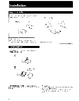
will not be used for a long time, remove the batteries. On battery life About half a year of normal operation can be expected when using the Sony SUM-3 (NS) batteries. When the batteries are run down, the remote commander will not operate the unit. In this case, replace both batteries with new - Sony STR-AV500 | Operating Instructions - Page 5
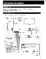
9) LJ OO • Turntable system (SeePage 7) O CD player (See page 8) i771 o L DAT deck (See page 8) ' -I I Tapedeck 1(See page 8) mmImQ • (See Page 9) To the second speaker syst to a wall outlet Notes Cord plugs and jacks are color coded. Red plugs and jacks are for right-channel (R) and white ones - Sony STR-AV500 | Operating Instructions - Page 6
best with speakers having nominal impedance from 8 to 16 ohms, at rated 55 watts minimum RMS per channel with an 8-ohm load from 20 - 20,000 Hz. Connecting the AM antenna Receiver --f - LOiOOO 0000000@e 0(0000010@CD of O. 'lock L-i For areas with difficult AM reception In areas with troubled - Sony STR-AV500 | Operating Instructions - Page 7
O Connecting the FM antenna I® O OO O O O O OO OOO OOOO OO OOO 1=3 Receiver U1 L-J rFor normal use Supplied ribbon antenna (or 300-ohm twin-lead) 3Eiar) 75Q 4J . • Connecting a Turntable System @do@ 00i INC %MIL O OOO OO O @@ OOO OO O @@ 700 Receiver Turntable system tc1 A 7 - Sony STR-AV500 | Operating Instructions - Page 8
RK-C74 toline outputs Tape deck wastee* Ike _ eirorik =D-----1 -'- © • to line inputs O Connecting a DAT (Digital Audio Tape) Deck Receiver :0 pp@ O! O O OO O @ aele (Di OOO@aOKDO! JR, (az ° oeueC) RK-C74 to line outputs DAT deck - mom+ . mien- mowt wiry E3 I ,, e O any - Sony STR-AV500 | Operating Instructions - Page 9
. eser to a wall outlet Caution Be careful that the total power consumption of each piece of equipment connected to the outlets on the receiver does not exceed 100 watts. Do not connect electrical home appliance such as an electric iron, fan, TV, or other high-wattage equipment to these - Sony STR-AV500 | Operating Instructions - Page 10
the individual connection diagram. Monitor TV VCR 2 (for palyback only) Speaker system ® (See page 11) VCR 1(for recording and playback) ( O C) @C,••• 0 00 ©0••• I=1 • Receiver ErE C-J oill Connecting a VCR _a open a 0 600 © 0 @ 0000 00066 Receiver RIF to a wall outlet 'DEO 2 VIDEO - Sony STR-AV500 | Operating Instructions - Page 11
® Connecting a Monitor TV Receiver O OOO ion O C00iO11• 0O OO el@ 'OO @ @ 1 1=1_ gb m®gym II 0 CD 0 I OH VMC-1S Monitor TV to video input mICL__,Iz. momy 11 - Sony STR-AV500 | Operating Instructions - Page 12
Parts Identification 4- - Refer to the pages indicated in 0 for details. BAND selectors (1) Display window fp 5 BAND GRAPHIC EQUALIZER 4 Remote control sensor SYSTEM POWER switch IP MO 0 TT ,"---. 1 HEADPHONES jack (stereo phone jack) SPEAKERS selectors (1) FM MODE button (P 12 - Sony STR-AV500 | Operating Instructions - Page 13
0 TUNING +/- buttons ID MEMORY button 10 la Numeric buttons ENTER button e) MUTING button and indicator VOLUME control knob and indicator 0 BALANCE control knob 0 SURROUND button and indicator fp PRESET +/- buttons (i) m® FUNCTION selectors 13 - Sony STR-AV500 | Operating Instructions - Page 14
Parts Identification Remote Commander RM-U80 1 2 3 1 \ Ek 4 14-4 I.I.I 5 12 44 Y 1.0. • I. • 0 6 IOOOO .1 M.O. 7 • I I • Lwow' 13 Lao! fk+ 8 14 = I = 9 .L....1. .-i- 10 15 11 } 14 - Sony STR-AV500 | Operating Instructions - Page 15
set on the VCR. If your VCR does not have one, set to VCR 1. If a Sony 8 mm VCR is connected, set to VCR 2. • PHONO buttons START: Starts record play. STOP do not operate on the STR-AV500.) [1] TV buttons VOL: Adjusts the TV sound level. CH: Selects the TV receiving channel. 3 VTR CHANNEL buttons - Sony STR-AV500 | Operating Instructions - Page 16
same listening level as before. Balance Adjustment To change the relative strength of the right and left speaker output Adjust BALANCE to correct stereo imaging, when the speaker position is not symmetrical. • Sound Quality Adjustment To equalize a program source Slide the equalizer controls upward - Sony STR-AV500 | Operating Instructions - Page 17
I Receiving FM/AM Broadcasts Tuning in a Station Directly-Direct Access Tuning SYSTEM POWER-ON 123 4 5 IZZl:=11=1 000 m Select SPEAKERS A or B. 1 Press TUNER. 2 Select FM or AM. 3 Press DIRECT. 4 Press the appropriate numeric buttons to enter the frequency. (See examples below). 5 Adjust the - Sony STR-AV500 | Operating Instructions - Page 18
Receiving FM!AM Broadcasts Tuning in an AM Station Manually-Manual Tuning When you do not know the frequency of the AM station, proceed as follows: SYSTEM POWER-ON I 2 314 =.0(= OOP PO= . k p_c rl ,', *4' 1 _ O CD Select SPEAKERS A or B. 1 Press TUNER. 2 Press AM. 3 Press "+" or "-" - Sony STR-AV500 | Operating Instructions - Page 19
a Station-Memory Preset A total of 20 FM/AM stations can be memorized in any desired sequence. SYSTEM POWER-ON 2 3 4 0 1 00 0 00 =1=1 Select SPEAKERS A or B. 'I Tune in the desired station. (See pages 17 and 18.) 2 Press MEMORY MEMORY indicator appears for a few seconds. 3 Select the desired - Sony STR-AV500 | Operating Instructions - Page 20
Receiving FM/AM Broadcasts Tuning in a Preset Station-Preset Tuning SYSTEM POWER-ON Method A 1 2 34 CI (1) Select SPEAKERS A or B. Method B Method A 1 Press TUNER. 2 Select the preset number. 3 Press ENTER. 4 Adjust the volume. Method B 1 Press TUNER. 2 Press "+" or "-" PRESET. Each time you - Sony STR-AV500 | Operating Instructions - Page 21
program. 3 Adjust the volume. FUNCTION PHONO CD VIDEO 1, 2 TAPE DAT Receiving a TV Program with FM Simulcast ivIonttor TV TV tuner or VCR SYSTEM POWER 2 IN 0 it • • • 0 00 0 MONITOR VIDEO OUT ./. .0 ' Select SPEAKERS 1 A or El. 1 Press VIDEO 1 or VIDEO 2. VIDEO 1: When the VHF antenna - Sony STR-AV500 | Operating Instructions - Page 22
the DAT or tape deck in the recording mode. 3 Start the desired program source. Tape Dubbing SYSTEM POWER-ON 3 Select SPEAKERS A or B. - - J , , ,==00=0==,..., 0 00 C 00 f- -T---1 0 o *1- T - 1--:-' to TAPE 1 REC OUT to DAT IN 2,4 Tape deck 1 (for recording) 1,4 Tape deck 2 or DAT - Sony STR-AV500 | Operating Instructions - Page 23
To operate the VCR, refer to its instruction manual. Recording Audio Programs To record an audio program source on a video tape, proceed as follows: SYSTEM POWER-ON 2,3 VCR 1 VIDEO 1 AUDIO OUT 1_,C= 00= 0=1,, MO C.= O 0 CI Select SPEAKERS A or B. Turntable system ••---- CD player Tape - Sony STR-AV500 | Operating Instructions - Page 24
source, thus making your own personalized video tape. SYSTEM POWER-O 2,3 VCR 2 Select SPEAKERS A or S. L Video Signals Audio signals VCR 1 1 4 Monitor TV Turntable system CD player Tape deck DAT deck Turn on the receiver and the equipment to be used. 1 Press VIDEO 2/CDV. 2 Insert a recorded - Sony STR-AV500 | Operating Instructions - Page 25
Troubleshooting Guide Before proceeding through the checklist below, examine the connections and the procedures outlined in the manual. Should any problem persist after you have checked the following items, consult your nearest Sony dealer. Broadcast program Video program PROBLEM CAUSE REMEDY - Sony STR-AV500 | Operating Instructions - Page 26
Troubleshooting guide Amplifier PROBLEM Severe hum or noise is heard. The remote commander does not operate. CAUSE The connecting cords are not of shielded type. A transformer, motor, TV or fluorescent light affects the connecting cord. The audio components are too close to a TV set. The receiver - Sony STR-AV500 | Operating Instructions - Page 27
Outputs REC OUT VIDEO (AUDIO) OUT Voltage 150 mV Impedance 10 kilohms SPEAKER A, B Accepts speakers of 8 - 16 ohms. HEADPHONES Accepts low and high impedance headphones. (1) AM loop antenna (1) Remote Commander RM-U80 Sony battery (NS) (2) (for the remote commander) SUM-3 Design and - Sony STR-AV500 | Operating Instructions - Page 28
automatically ON SYSTEM POWER TUNER TUNING or Stop tuning TUNER Tuning in an AM station manually ON SYSTEM POWER TUNER TUNING 7 or Memorizing a station Tune in the desired station. TUNER Press desired number 2 13 16 L_ _J I9 I PRESET or ENT R Sony Corporation Printed in Korea
-
 1
1 -
 2
2 -
 3
3 -
 4
4 -
 5
5 -
 6
6 -
 7
7 -
8
-
9
-
10
-
11
-
12
-
13
-
14
-
15
-
16
-
17
-
18
-
19
-
20
-
21
-
22
-
23
-
24
-
25
-
26
-
27
-
28
 |
 |

SONY
3-769-887-22
(1)
FM
Stereo/FM-AM
Receiver
Operating
Instructions
Before
operating
the
unit,
please
read
this
manual
thoroughly
and
retain
it
for
future
reference.
Owner's
Record
The
model
and
serial
numbers
are
located
at
the
rear.
Record
the
serial
number
in
the
space
provided
below.
Refer
to
these
numbers
whenever
you
call
upon
your
Sony
dealer
regarding
this
product.
Model
No.
STR-AV500
Serial
No.
SONY
ti
0
A,I)'CVID
CONTROL
CENTL:5
©
1988
by
Sony
Corporation