Sony STR-AV500 Operating Instructions - Page 6
capability
 |
View all Sony STR-AV500 manuals
Add to My Manuals
Save this manual to your list of manuals |
Page 6 highlights
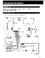
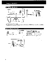
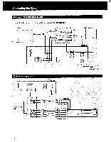
Connecting the System 0 Connecting the Speakers Receiver I,I 0,000 000000'01001 p @CD el0 00001 l= i ism -0 L Right speaker 1 Left speaker O O • • To the second speaker system. O O 2 15 mm O O I Speaker impedance and power capability This receiver is designed to work best with speakers having nominal impedance from 8 to 16 ohms, at rated 55 watts minimum RMS per channel with an 8-ohm load from 20 - 20,000 Hz. Connecting the AM antenna Receiver --f - LOiOOO 0000000@e 0(0000010@CD of O. 'lock L-i For areas with difficult AM reception In areas with troubled reception, connect a 6- to 15-meter (20- to 50-foot) insulated wire to the AM antenna terminal. Extend this out of doors if possible, keeping the greater portion horizontal. (There is no need to disconnect the supplied antenna.) Adjust the direction. 3:00 0 4r1 75() Supplied loop- timmo) free antenna I 6
-
 1
1 -
 2
2 -
 3
3 -
 4
4 -
 5
5 -
 6
6 -
 7
7 -
 8
8 -
 9
9 -
 10
10 -
 11
11 -
 12
12 -
13
-
14
-
15
-
16
-
17
-
18
-
19
-
20
-
21
-
22
-
23
-
24
-
25
-
26
-
27
-
28
 |
 |
