Sony STR-D511 Operating Instructions - Page 5
Hooking, System
 |
View all Sony STR-D511 manuals
Add to My Manuals
Save this manual to your list of manuals |
Page 5 highlights
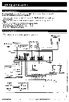
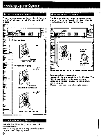
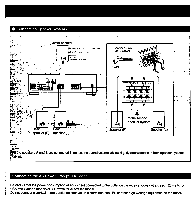
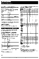
Hooking Up the System Notes on Connections At first, this section describes about the connection with the other equipments, the antenna connection, speaker connection and then the AC power connection. • Do not connect the power cord to an AC outlet nor press the POWER switch before accomplishing all other connections. • The cable connectors should be fully inserted into the jacks. Loose connection may cause hum and noise. • Jacks and plugs of the connecting cord are color-coded as follows: Red jacks and plugs: For the right channel of audio signals White jacks and plugs: For the left channel of audio signals Yellow jacks and plugs: For video signals Connecting Equipment The numbers correspond to the following details on page 6 and 7. o AM antenna o FM antenna Rear speaker system I Monitor TV Ito VIDEO IN Speaker system (A speakers) 0 T iO0 J. • (Th tfi IMMO Ipr 11 11-. EP' 1.don 4 C, ft CIAO to OUTPUT Turntable to OUTPUT CD player TAPE deck or DAT deck to LINE IN, • to LINE OUT Receiver White L © R Red Other equipment White L *C) R Red Center speaker to AUDIONIDEO OUTPUT to AUDIONIDEO INPUT to AUDIONIDEO OUTPUT 1 0 O Speaker system (B speakers) VCR 1 VCR 2/LD player 5 - - - "": • T*
-
 1
1 -
 2
2 -
 3
3 -
 4
4 -
 5
5 -
 6
6 -
 7
7 -
 8
8 -
 9
9 -
 10
10 -
 11
11 -
12
-
13
-
14
-
15
-
16
-
17
-
18
-
19
-
20
-
21
-
22
-
23
-
24
 |
 |
