Sony STR-DE945 Operating Instructions - Page 52
CONTROL A1, Control System, Basic Functions, Connections, indicators light together.
 |
View all Sony STR-DE945 manuals
Add to My Manuals
Save this manual to your list of manuals |
Page 52 highlights
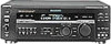
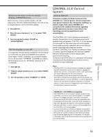
CONTROL A1 Control System Connections Connect monaural (2P) mini-plug cords in series to the CONTROL A1 jacks on the back of each component. You can connect up to ten CONTROL A1 compatible components in any order. However, you can connect only one of each type of component (i.e., 1 CD player, 1 MD deck, 1 tape deck and 1 receiver). (You may be able to connect more than one CD player or MD deck, depending on the model. Refer to the operating instructions supplied with the respective component for details.) Example Amplifier CD MD Tape Other (Receiver) player deck deck component In the CONTROL A1 control system, the control signals flow both ways, so there is no distinction of IN and OUT jacks. If a component has more than one CONTROL A1 jack, you can use either one, or connect different components to each jack. Jacks and connection examples CONTROL A1 CONTROL A1 CD player MD deck On CONTROL A1 jacks and connections It is possible to make connections between CONTROL A1 and CONTROL A1 jacks. For details regarding particular connections or setup options, refer to the Operating Instructions supplied with the component(s). About the connecting cord Some CONTROL A1 compatible components are supplied with a connecting cord as an accessory. In this case, use the connecting cord for your connection. When using a commercially available cord, use a monaural (2P) mini-plug cord less than 2 meters long, with no resistance (like the Sony RK-G69HG). Basic Functions The CONTROL A1 functions will operate as long as the component you want to operate is turned on, even if all of the other connected components are not turned on. Automatic function selection When you connect a CONTROL A1 compatible Sony amplifier (or receiver) to other Sony components using monaural mini-plug cords, the function selector on the amplifier (or receiver) automatically switches to the correct input when you press the play button on one of the connected components. Notes • You must connect a CONTROL A1 compatible amplifier (receiver) using a monaural mini-plug cord in order to take advantage of the automatic function selection feature. • This function only works when the components are connected to the amplifier (or receiver) inputs according to the names on the function buttons. Certain receivers allow you to switch the names of the function buttons. In this case, refer to the Operating Instructions supplied with the receiver. • When recording, do not play any components other than the recording source. It will cause the automatic function selection to operate. Synchronized recording This function lets you conduct synchronized recording between the selected source and recorder components. 1 Set the function selector on the amplifier (or receiver) to the source component. 2 Set the source component to pause mode (make sure both the ( and P indicators light together). 3 Set the recorder component to the REC-PAUSE mode. 4 Press PAUSE on the recorder component. The source component is released from the pause mode, and recording begins shortly thereafter. When playback ends from the source component, recording stops. Notes • Do not set more than one component to the pause mode. • Certain recorder components may be equipped with a special synchronized recording function that uses the CONTROL A1 Control System, like "CD Synchro Dubbing". In this case, refer to the Operating Instructions supplied with the recorder component. Other Operations 52
-
 1
1 -
2
-
3
-
4
-
5
-
6
-
7
-
8
-
9
-
10
-
11
-
12
-
13
-
14
-
15
-
16
-
17
-
18
-
19
-
20
-
21
-
22
-
23
-
24
-
25
-
26
-
27
-
28
-
29
-
30
-
31
-
32
-
33
-
34
-
35
-
36
-
37
-
38
-
39
-
40
-
41
-
42
-
43
-
44
-
45
-
46
-
 47
47 -
 48
48 -
 49
49 -
 50
50 -
 51
51 -
 52
52 -
 53
53 -
 54
54 -
 55
55 -
 56
56 -
 57
57 -
58
-
59
-
60
-
61
-
62
-
63
-
64
 |
 |