Sony UP895 Service Manual - Page 19
Removal of MA-99 Board, 2-3-3. Removal of Switching Regulator
 |
View all Sony UP895 manuals
Add to My Manuals
Save this manual to your list of manuals |
Page 19 highlights
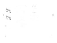
2-3-2. Removal of MA-99 Board 1. Remove the top cover. (Refer to Section 2-2.) 2 Screw (BTP 3x8) 1 Tapping screws (M3) 3 Rear panel 2-3-3. Removal of Switching Regulator 1. Remove the top cover. (Refer to Section 2-2.) 2. Remove the front panel, door panel and power switch rod. (Refer to Section 2-3-1.) 3. Remove the MA-99 board. (Refer to Section 2-3-2.) 1 Tapping screw (M3) 3 CN201 2 Sheeld plate 1 Tapping screw (M3) 5 Tapping screws (M3) 4 CN14 4 CN2 4 CN8 4 CN12 4 CN1 5 Tapping screws (M3) 4 CN13 4 CN7 4 CN3 6 MA-99 board 4 CN9 6 Switching regulator 4 Screws (PS 3x6) 4 Screws (PS 3x6) UP-895/(E) 2-3
-
 1
1 -
2
-
3
-
4
-
5
-
6
-
7
-
8
-
9
-
10
-
11
-
12
-
13
-
 14
14 -
 15
15 -
 16
16 -
 17
17 -
 18
18 -
 19
19 -
 20
20 -
 21
21 -
 22
22 -
 23
23 -
 24
24 -
25
-
26
-
27
-
28
-
29
-
30
-
31
-
32
-
33
-
34
-
35
-
36
-
37
-
38
-
39
-
40
-
41
-
42
-
43
-
44
-
45
-
46
-
47
-
48
-
49
-
50
-
51
-
52
-
53
-
54
-
55
-
56
-
57
-
58
-
59
-
60
-
61
-
62
-
63
-
64
-
65
-
66
-
67
-
68
-
69
-
70
-
71
-
72
-
73
-
74
-
75
-
76
-
77
-
78
-
79
-
80
-
81
-
82
-
83
-
84
 |
 |

2-3
UP-895/(E)
2-3-2.
Removal of MA-99 Board
1.
Remove the top cover. (Refer to Section 2-2.)
4 CN7
6
MA-99 board
4 CN2
4 CN12
5
Tapping screws (M3)
5 Tapping
screws (M3)
4 CN14
4 CN1
4 CN8
4 CN13
4 CN3
4 CN9
4 Screws
(PS 3
x
6)
4
Screws (PS 3
x
6)
1 Tapping
screw (M3)
1
Tapping screw
(M3)
3 CN201
6 Switching
regulator
2
Sheeld plate
1 Tapping
screws
(M3)
3
Rear panel
2 Screw
(BTP 3
x
8)
2-3-3.
Removal of Switching Regulator
1.
Remove the top cover. (Refer to Section 2-2.)
2.
Remove the front panel, door panel and power switch
rod. (Refer to Section 2-3-1.)
3.
Remove the MA-99 board. (Refer to Section 2-3-2.)