Sony UP895 Service Manual - Page 9
Connection, Setting Up the Printer, Setting the Slide Switches on the, Paper Tray, Rear Panel
 |
View all Sony UP895 manuals
Add to My Manuals
Save this manual to your list of manuals |
Page 9 highlights
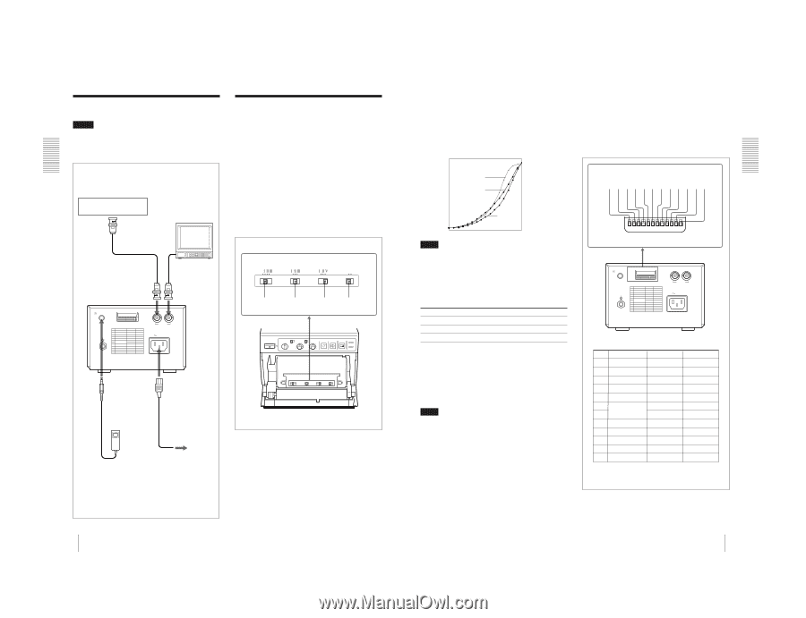
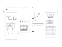
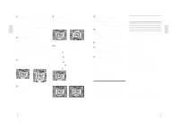
1-3 UP-895/(E) Preparation Connection/Setting Up the Printer Connection Notes • Turn off the power to each device before making any connections. • Connect the AC power cord last. Video equipment to video output connector Color/black and white video monitor Setting Up the Printer You can set the printer to the desired specifications using two kinds of switches. • Slide switches on the paper tray inside the front door You can easily set the printer specifications most frequently used in daily operation, such as selection of the paper type and printout quality. • DIP switches on the rear panel You can set the print mode and other settings you do not need to change frequently Setting the Slide Switches on the Paper Tray The factory settings are as follows. Supplied coaxial connecting cable (BNC y BNC) to video input connector Connecting cable (not supplied) to VIDEO IN to VIDEO OUT REMOTE UP DOWN DIP SW t IN T OUT VIDEO AC IN SHARPNESS OFF GAMMA PAPER TYPE SMOOTHING OFF ON 1 2 3 4 to REMOTE to AC IN Supplied AC power cord RM-91 Remote control unit (not supplied) to wall outlet A SHARPNESS switch Adjusts the sharpness of the printout. OFF: Not to emphasize an outline of the printout, set the switch to this position. I, II, III: To make a sharper outline, set the switch to the proper position. In I, II and III order, the printout becomes sharper. 22 Preparation B GAMMA switch Sets the tone of printouts (density gradation). I: Soft gradation II: Standard III: Hard gradation The diagram below shows the curve of density graduation for each tone. High I II Print density III Low 0 Gradation 255 Note This switch is effective only when you use paper types UPP-110HD or UPP-110HG, that is, when the PAPER TYPE switch C is set to either II or V. C PAPER TYPE switch Selects the paper type. Set the switch to the type of paper to be used. Type of paper UPP-110S UPP-110HD UPP-110HG Switch position I (Normal) II (High density) V (High glossy) D SMOOTHING switch Selects the line density. OFF: Normally keep this switch to this position. ON: To set the print line density to high density and obtain the better print quality, set the switch to this position. However, the printing speed is slower than at the OFF position. Note This switch becomes effective under the following conditions. • When the image size selector on the front panel is set to either SML or NOR and STD/SIDE selector is set to STD, and ASPECT of DIP switch C on the rear panel is set to 4 : 3. • When the image size selector is set to a position other than SML and NOR and ASPECT of DIP switch C is set to 1 : 1. Under any other conditions except those above, the print line density is not set to high and the print quality is standard even if you set the switch to ON. Setting Up the Printer Setting the DIP Switches on the Rear Panel To change the DIP switch settings Use a small pointed tool such as a small screwdriver. The factory settings are as follows. 1 2 3 4 5 6 7 8 9 q; qa qs DIP SW UP DOWN 1 2 3 4 5 6 7 8 9 10 11 12 REMOTE UP DOWN DIP SW t IN T OUT VIDEO AC IN UP-895MD/895CE DIP SW FUNCTION TABLE NO. FUNCTION 1 INTERRUPT 2 POSTFEED 3 ASPECT 4 MEMORY 5 DIRECTION 6 SCAN 7 8 OUTPUT 9 AGC 10 RESERVED 11 INPUT 12 75 Ω SW-DOWN ON ON 4:3 FRAME NORM - WIDE 1 THRU OFF - B & W ON SW-UP OFF OFF 1:1 FIELD REV WIDE 2 NORM EE ON - COLOR OFF SW-DOWN or SW-UP indicated in parentheses shows the switch position. Preparation 23 Preparation
-
 1
1 -
2
-
3
-
 4
4 -
 5
5 -
 6
6 -
 7
7 -
 8
8 -
 9
9 -
 10
10 -
 11
11 -
 12
12 -
 13
13 -
 14
14 -
15
-
16
-
17
-
18
-
19
-
20
-
21
-
22
-
23
-
24
-
25
-
26
-
27
-
28
-
29
-
30
-
31
-
32
-
33
-
34
-
35
-
36
-
37
-
38
-
39
-
40
-
41
-
42
-
43
-
44
-
45
-
46
-
47
-
48
-
49
-
50
-
51
-
52
-
53
-
54
-
55
-
56
-
57
-
58
-
59
-
60
-
61
-
62
-
63
-
64
-
65
-
66
-
67
-
68
-
69
-
70
-
71
-
72
-
73
-
74
-
75
-
76
-
77
-
78
-
79
-
80
-
81
-
82
-
83
-
84
 |
 |