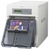
Sony UPDR200 Operating Instructions - Page 6
Scrap receptacle Filter cover USB connector POWER switch - printer
 |
View all Sony UPDR200 manuals
Add to My Manuals
Save this manual to your list of manuals |
Page 6 highlights
Introduction K Scrap receptacle (page 13) Margins of empty space are crated between each printout. These margins are cut off during printing and dropped into this receptacle. Rear L Filter cover (page 26) The filter for the printer's cooling fan is attached to this cover. M USB connector (page 8) Connects to a computer equipped with USB interface (conforming to USB 2.0) via the supplied USB cable. N ! POWER switch (page 18) Press this to turn the printer on and off. O - AC IN connector (page 8) Connect the power cord here. 6 Location and Function of Parts and Controls

Introduction
Location and Function of Parts and Controls
6
K
Scrap receptacle (page 13)
Margins of empty space are crated between each
printout. These margins are cut off during printing
and dropped into this receptacle.
L
Filter cover (page 26)
The filter for the printer’s cooling fan is attached to
this cover.
M
USB connector (page 8)
Connects to a computer equipped with USB
interface (conforming to USB 2.0) via the supplied
USB cable.
N
!
POWER switch (page 18)
Press this to turn the printer on and off.
O
-
AC IN connector (page 8)
Connect the power cord here.
Rear


