Sony XDS1000 User Manual (XDS-1000 Operation Manual for Firmware Version 1.1) - Page 81
silence [silnc], Menu items in the 800s, relating to audio control
 |
View all Sony XDS1000 manuals
Add to My Manuals
Save this manual to your list of manuals |
Page 81 highlights
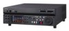
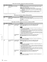
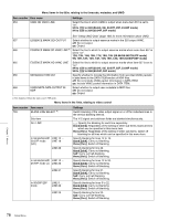
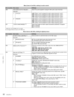
Menu items in the 700s, relating to video control Item number Item name Settings 743 PR LEVEL (HD) Adjust the PR level of the high-definition video signal output from the HD-SDI OUTPUT or HDMI OUTPUT connectors. -2048 to 0 to 846 745 SETUP LEVEL (HD) Adjust the setup level of the high-definition video signal output from the HD-SDI OUTPUT or HDMI OUTPUT connectors. -272 to 0 to 272 746 SYNC PHASE (HD) Control the H sync phase of the high-definition video signal output from the HD-SDI OUTPUT or HDMI OUTPUT connectors. -128 to 0 to 127 747 FINE (HD) Fine control the H sync phase of the high-definition video signal output from the HD-SDI OUTPUT or HDMI OUTPUT connectors. 0 to 1023 a) Not displayed when the unit is in 23.98P mode. Menu items in the 800s, relating to audio control Item number Item name 802 DIGITAL AUDIO MUTING IN SHUTTLE MODE 807 AUDIO OUTPUT PHASE 808 INTERNAL AUDIO SIGNAL GENERATOR 815 AUDIO SAMPLING RATE CONVERTER 823 NON-AUDIO FLAG PB Sub-item 1 CH1/CH2 2 CH3/CH4 3 CH5/CH6 4 CH7/CH8 824 ANALOG LINE OUTPUT SELECT Settings Set the audio muting conditions during shuttle playback. off: Not muted. on: Muted. Set the output timing of digital audio playback signals (HD-SDI, SDI, AES/EBU only) as a hexadecimal value, with 80 as a reference position. Output timing is earlier for values smaller than 80 and later for values greater than 80. (80, 128 samples = approx. 2.7 ms, 80, 1 sample = approx. 20 μs) 0 to 80 to FF: Values can be set in this range. Select the operation of the internal audio test signal generator. off: Do not output test signal. silence [silnc]: Silent signal 1kHz sine [1kHz]: 1 kHz, -20 dB FS sine wave signal When you set the INT SG item on page P1 INPUT of the function menu to "ON", the internal signal generator operates and outputs simultaneous test signals to channels 1 to 8 (see page 42). Select the mode of operation of the sampling rate converter for AES/ EBU input to channels 1 to 8. off: Do not operate. on: Operate. Control non-audio flags in digital audio output. During playback (except in E-E mode), set non-audio flags in digital audio output to the following states. on: Set to on (data is non-audio.) auto: Set as follows. • When data is read from media and confirmed: Follow the data. • When data from media is not confirmed: Maintain current state. Select the analog audio signals (tracks 1 to 8) to be assigned to audio output channels 1 and 2. tr1/2: Tracks 1 and 2 assigned to audio output channels 1 and 2. tr3/4: Tracks 3 and 4 assigned to audio output channels 1 and 2. tr5/6: Tracks 5 and 6 assigned to audio output channels 1 and 2. tr7/8: Tracks 7 and 8 assigned to audio output channels 1 and 2. Chapter 7 Menus 81 Setup Menu
-
 1
1 -
2
-
3
-
4
-
5
-
6
-
7
-
8
-
9
-
10
-
11
-
12
-
13
-
14
-
15
-
16
-
17
-
18
-
19
-
20
-
21
-
22
-
23
-
24
-
25
-
26
-
27
-
28
-
29
-
30
-
31
-
32
-
33
-
34
-
35
-
36
-
37
-
38
-
39
-
40
-
41
-
42
-
43
-
44
-
45
-
46
-
47
-
48
-
49
-
50
-
51
-
52
-
53
-
54
-
55
-
56
-
57
-
58
-
59
-
60
-
61
-
62
-
63
-
64
-
65
-
66
-
67
-
68
-
69
-
70
-
71
-
72
-
73
-
74
-
75
-
 76
76 -
 77
77 -
 78
78 -
 79
79 -
 80
80 -
 81
81 -
 82
82 -
 83
83 -
 84
84 -
 85
85 -
 86
86 -
87
-
88
-
89
-
90
-
91
-
92
-
93
-
94
-
95
-
96
-
97
-
98
-
99
-
100
-
101
-
102
-
103
-
104
-
105
-
106
-
107
-
108
-
109
-
110
-
111
-
112
-
113
-
114
-
115
-
116
 |
 |