Stihl RZ 142 Instruction Manual - Page 21
Attaching a Trailer
 |
View all Stihl RZ 142 manuals
Add to My Manuals
Save this manual to your list of manuals |
Page 21 highlights
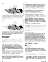
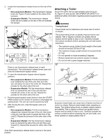
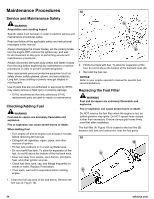
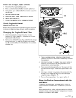
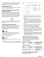
2. Locate the transmission release levers on the rear of the unit. • Non-suspension Models: The transmission release levers (A, Figure 16) are located on the sides of the bumpers. • Suspension Models: The transmission release levers (B) are located on the rear of the unit beneath the bumper. 16 Attaching a Trailer Secure the trailer with an appropriately sized clevis pin (A, Figure 17) and clip (B). See OPERATOR SAFETY for additional safety information regarding towed equipment and towing. WARNING Towing Hazard Towed loads can be hazardous and cause loss of control on slopes. The surface being driven on greatly impacts traction and stability. Wet or slippery surfaces can greatly reduce traction and the ability to stop or turn. Carefully evaluate the surface conditions before operating the unit with towed equipment. • The maximum gross (trailer & load) weight of the trailer should not exceed 200 lbs (91 kg). • The maximum tongue weight should not exceed 20 lbs (9,1 kg). • Do not operate on slope exceeding 5 degrees. • Reduce speed and use extreme caution on slopes. • Do not tow with a grass bagger attached. There is one transmission release lever on each transmission. The transmission release levers open and close the transmission bypass valves. 3. To open the transmission bypass valves (bypass position): • Non-suspension Models: Pull the transmission lever towards the rear of the unit, then up in the slot, and allow it to rest in the notch (C). Repeat this process for the other side of the unit. • Suspension Models: Pull the transmission release lever out towards the rear of the unit and then towards the center of the unit (D). Repeat this process for the other side of the unit. 4. Pivot the ground speed control levers in from the START/ PARK position to the neutral 'N' position to disengage the parking brake. The unit can now be pushed by hand. 5. After moving the unit, close the bypass valve (run position): • Non-suspension Models: Pull the transmission release lever towards the rear of the unit, then down in the slot, and then push it towards the front of the unit (E). Repeat the process for the other side of the unit. • Suspension Models: Pull the transmission release lever out towards the side of the unit and then push forward (F). Repeat this process for either side of the unit. Note: Both transmission release levers must be in the same position. 17 Excessive towed loads can cause loss of traction and loss of control on slopes. Reduce towed weight when operating on slopes. The surface being driven on greatly impacts traction and stability. Wet or slippery surfaces can greatly reduce traction and the ability to stop or turn. Carefully evaluate the surface conditions before operating the unit and trailer, and never operate on slopes greater than 5°. 21
-
 1
1 -
2
-
3
-
4
-
5
-
6
-
7
-
8
-
9
-
10
-
11
-
12
-
13
-
14
-
15
-
 16
16 -
 17
17 -
 18
18 -
 19
19 -
 20
20 -
 21
21 -
 22
22 -
 23
23 -
 24
24 -
 25
25 -
 26
26 -
27
-
28
-
29
-
30
-
31
-
32
-
33
-
34
-
35
-
36
-
37
-
38
-
39
-
40
-
41
-
42
-
43
-
44
 |
 |
