Stihl RZ 142 Instruction Manual - Page 26
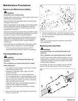
Containing Spilled Fluids and Proper
 |
View all Stihl RZ 142 manuals
Add to My Manuals
Save this manual to your list of manuals |
Page 26 highlights
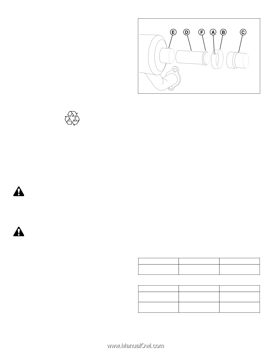
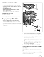
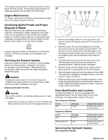
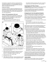
The maximum air pressure for cleaning purposes must be below 205 kPa (30 psi). The maximum water pressure for 21 cleaning purposes must be below 275 kPa (40 psi). Engine Maintenance For engine maintenance schedules and procedures, please refer to the engine operator's manual. Containing Spilled Fluids and Proper Disposal of Waste Make sure that fluids are contained when performing inspection, maintenance, testing, adjustment, and repair of the unit. Be prepared to collect the fluid with suitable leakproof containers before opening or disassembling any component containing fluids. Do not pour waste onto the ground, down a drain, or into any source of water. Improper disposal of waste can threaten the environment. Dispose of all fluids according to local regulations and mandates. Servicing the Exhaust System Inspect the muffler for cracks, corrosion, or other damage. Remove the spark arrester, if equipped, and inspect for damage or carbon blockage. If replacement parts are required, make sure to use only original equipment replacement parts. WARNING Replacement parts must be of the same design and installed in the same position as the original parts. Other parts could result in damage or an injury. Replacing the Spark Arrester: CAUTION Wait until the muffler is cool before working around or near the muffler. 1. Loosen the set screw (A, Figure 21) on the retaining ring (B) and slide off over the tip of the tailpipe extension (C). 2. Remove the tailpipe extension. You may need to use pliers to remove the tailpipe extension if it is stuck due to corrosion. 3. Slide the screen (D) out of the tailpipe (E) and shake the screen to remove the built up soot and carbon. The amount of carbon collected will vary depending on the fuel used, air quality, engine age, and condition. (A soft non-metallic brush may be required to fully clean the screen). 4. Carefully inspect the screen for any tears, rips or any other damage which will prevent the screen from operating properly. Replace screen if damaged. 5. Slide the screen into the tailpipe of the muffler until the retaining lip (F) is sitting against the tip of the tailpipe. 6. Slide the tailpipe extension over the tailpipe of the muffler. The extension is designed to fit tightly and you may need to twist it to get it to slide on. 7. Slide the retaining ring over the tailpipe extension until it circles the expanded section of the extension where the muffler tailpipe and tailpipe extension overlap. Torque set screw to 38 in-lbs (4,3 Nm). Fuse Identification and Location The electrical system for this unit is equipped with replaceable fuse(s). See the chart below for the circuit, amperage, and approximate location of the fuses. Non-suspension Models: Circuit Main Amperage 20 amp Approximate Location Center of the unit and near the battery. Suspension Models: Circuit Main USB Charging Port Amperage 20 amp 5 amp Approximate Location Center of the unit and near the battery. Center of the unit and near the battery. Servicing the Hydraulic System Non-Suspension Models: 26 stihlusa.com
-
 1
1 -
2
-
3
-
4
-
5
-
6
-
7
-
8
-
9
-
10
-
11
-
12
-
13
-
14
-
15
-
16
-
17
-
18
-
19
-
20
-
 21
21 -
 22
22 -
 23
23 -
 24
24 -
 25
25 -
 26
26 -
 27
27 -
 28
28 -
 29
29 -
 30
30 -
 31
31 -
32
-
33
-
34
-
35
-
36
-
37
-
38
-
39
-
40
-
41
-
42
-
43
-
44
 |
 |