Stihl RZ 142 Instruction Manual - Page 30
Seat And Ground Speed Control Lever, Adjustments
 |
View all Stihl RZ 142 manuals
Add to My Manuals
Save this manual to your list of manuals |
Page 30 highlights
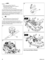
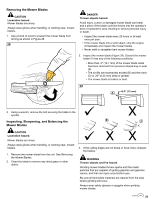
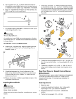
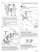
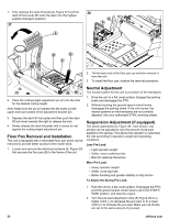
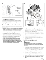
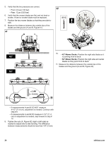
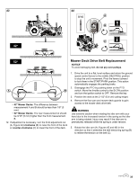
5. Use a grinder, hand file, or electric blade sharpener to sharpen the mower blades by removing an equal amount of material from the cutting edge of each end of the blade. 6. Keep the original bevel (A, Figure 30) when grinding. DO NOT change the mower blade bevel. 30 1. Install each blade with the airlifts (A, Figure 32) pointing up towards the mower deck as shown. Install the concave side of the washer (B) towards the blade. Install the blade mounting bolt (C) hand tight to hold the washer and blade onto the shaft (make sure the blade is fully seated onto the shaft). 32 7. The mower blade should have a maximum of 1/64" (0,40 mm) cutting edge (B) or less. CAUTION Thrown objects hazard. An unbalanced mower blade can create excessive vibration and damage the unit, or cause mower blade failure resulting in thrown debris. Be sure blade is balanced before installing. 8. Clamp a nail in a bench vise, hang the blade on the nail, and position the blade in a level horizontal position as shown in Figure 31. 31 9. Check the balance of the blade. If either end of the blade moves downward the end that moves downward is heavier than the other. Sharpen the heavy end until balance is achieved. 10. Repeat the process until the mower blade remains in the horizontal, level position. Installing Mower Blades CAUTION Laceration hazard Mower blades are sharp. Always wear gloves when handling, or working near, mower blades. 2. Tighten the blade mounting bolt to 50 - 60 ft. lbs. (68 - 81 Nm) of torque while holding onto the pulley bolt (D) with a wrench. 3. Tighten the pulley bolt to 50 - 60 ft. lbs. (68 - 81 Nm) of torque while holding onto the blade mounting bolt with a wrench. Seat And Ground Speed Control Lever Adjustments The seat and ground speed control levers should be adjusted so that the ground speed control levers can be moved through their full range of motion without contacting the operator's legs. Seat Adjustment 1. Raise the seat. 2. Loosen the adjustment hardware (A or B, Figure 33, depending on seat type) under the seat base. 3. Slide the seat forward or backward to the desired position. 4. Tighten the hardware to 80 lb-in (9 Nm). 30 stihlusa.com
-
 1
1 -
2
-
3
-
4
-
5
-
6
-
7
-
8
-
9
-
10
-
11
-
12
-
13
-
14
-
15
-
16
-
17
-
18
-
19
-
20
-
21
-
22
-
23
-
24
-
 25
25 -
 26
26 -
 27
27 -
 28
28 -
 29
29 -
 30
30 -
 31
31 -
 32
32 -
 33
33 -
 34
34 -
 35
35 -
36
-
37
-
38
-
39
-
40
-
41
-
42
-
43
-
44
 |
 |
