Stihl RZ 142 Instruction Manual - Page 27
Lubrication
 |
View all Stihl RZ 142 manuals
Add to My Manuals
Save this manual to your list of manuals |
Page 27 highlights
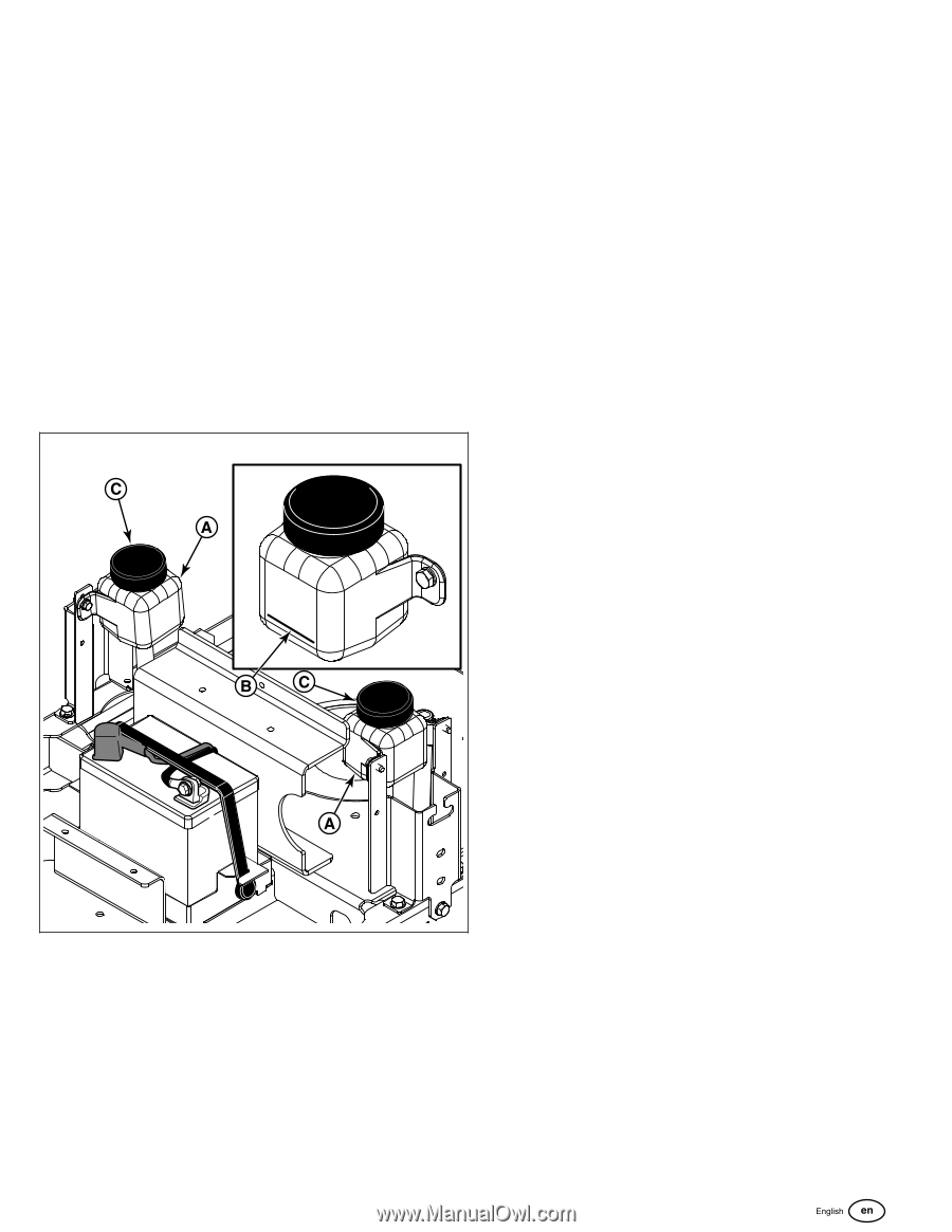
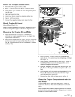
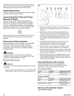
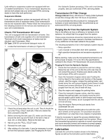
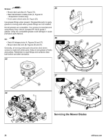
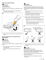
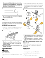
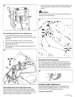
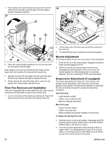
Units without a suspension system are equipped with two (2) sealed transmissions. If your transmission requires any service work please see your authorized STIHL servicing dealer to have this work performed. Suspension Models: Units with a suspension system are equipped with two (2) transmissions and oil expansion tanks. Each transmission has its own expansion tank. Please follow the instructions in the following sections for the service and maintenance for your unit's transmissions. Check / Fill Transmission Oil Level This unit is equipped with two transmission oil tanks. One transmission oil tank only supplies oil to one transmission. The level of oil in both transmission oil tanks must be checked, and if necessary, filled. Oil Type: 20W-50 conventional detergent motor oil. 1. Locate the transmission oil tanks (A, Figure 22). 22 2. Check the oil level when the unit is cold. The oil should be up to the "FULL COLD" mark (B). If the oil is below this level, proceed to step #3. 3. Before removing the tank caps (C), make sure the area around the tank cap and fill neck of the tank is free of dust, dirt, or other debris. Remove the tank cap. 4. Add oil up to the "FULL COLD" mark. 5. Reinstall the tank caps. 6. After adding oil to the tanks, it may be necessary to purge air from the hydraulic system. See Purging the Air from the Hydraulic System procedure. If the unit is not driving properly, see your authorized STIHL servicing dealer. Transmission Oil Filter Change Change Interval: Every 400 Hours or Yearly (Initial hydraulic oil and filter change after first 100 hours of operation). It is recommended that the procedure for changing the hydraulic oil and transmission filter be performed by an authorized STIHL servicing dealer. Purging the Air from the Hydraulic System Due to the effects air has on efficiency in hydraulic drive systems, it is critical that it be purged from the system. These purge procedures should be implemented any time a hydraulic system has been opened to facilitate maintenance or any additional oil has been added to the system. The resulting symptoms of air in the hydraulic system may be: • Noisy operation. • Lack of power or drive after short term operation. • High operation temperature and excessive expansion of oil. Before starting, make sure the transaxles/transmissions are at the proper oil levels. If it is not, fill to the specifications outlined in the Check / Fill Transmission Oil Level procedure. Purging Air from the Hydraulic System: 1. Chock the front wheels to prevent the unit from rolling. Raise the rear of the unit so that the unit's rear tires do not contact the ground. Position jack stands under the rear bumper of the unit to secure it. 2. Open the transaxle's bypass valves (see Pushing the Unit by Hand for the location and function of the bypass valves), start the engine, release the parking brake, and slowly move the unit's ground speed control levers in both forward and reverse directions (5 to 6 times), as air is purged from the unit, the oil level will drop. 3. Stop the engine and engage the parking brake. 4. Close the transaxle's bypass valves, start the engine, release the parking brake, and slowly move the unit's ground speed control levers in both forward and reverse directions (5 to 6 times), as air is purged from the unit, the oil level will drop. 5. Stop the engine. Remove the jack stands from underneath the unit. 6. Repeat the process detailed above but with the unit's drive wheels on the ground. The procedure should be performed in an area free of any objects or bystanders. It may be necessary to repeat the process detailed above until all the air is completely purged from the system. When the transaxles/transmissions operate at normal noise levels and move smoothly forward and reverse at normal speeds, then the transaxles/transmissions are considered purged. Lubrication Lubricate the unit at the location shown in the following figures as well as the lubrication points listed below. 27
-
 1
1 -
2
-
3
-
4
-
5
-
6
-
7
-
8
-
9
-
10
-
11
-
12
-
13
-
14
-
15
-
16
-
17
-
18
-
19
-
20
-
21
-
 22
22 -
 23
23 -
 24
24 -
 25
25 -
 26
26 -
 27
27 -
 28
28 -
 29
29 -
 30
30 -
 31
31 -
 32
32 -
33
-
34
-
35
-
36
-
37
-
38
-
39
-
40
-
41
-
42
-
43
-
44
 |
 |