TASCAM Celesonic US-20x20 Reference Manual - Page 4
Names and functions of parts
 |
View all TASCAM Celesonic US-20x20 manuals
Add to My Manuals
Save this manual to your list of manuals |
Page 4 highlights
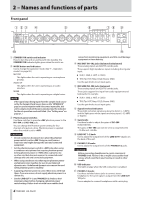
2 - Names and functions of parts Front panel 1 STANDBY/ON switch and indicator Press to turn the unit on and to put it into standby. The STANDBY/ON indicator lights green when the unit is on. 2 MODE button and indicators Use to change the operation mode. (See "7 - Operation modes" on page 28.) MIC PRE This lights when the unit is operating as a microphone preamp. AUDIO I/F This lights when the unit is operating as an audio interface. MIXER This lights when the unit is operating as a digital mixer. NOTE If the signal stops being input from the sample clock source set by the Sample Clock Source item on the "INTERFACE" page or synchronization with it becomes impossible, this unit's sample clock will become unlocked and the indicator for the set operation mode will blink. (See "Setting area" on page 21.) 3 Phantom power switches Use these switches to provide +48V phantom power to the IN1-IN4 and IN5-IN8 jacks. You can change the Phantom power setting for four channels of inputs at a time. Phantom power is supplied when the switch is set to +48V. CAUTION • Do not connect or disconnect mics when the phantom power switch is set to +48V. Doing so could cause a loud noise and might damage this unit and connected equipment. • Set the phantom power switch to +48V only when using a condenser microphone that requires phantom power. Setting phantom power to +48V when a dynamic mic or other mic that does not require it is connected could damage this unit and connected equipment. • When using condenser mics that require phantom power and dynamic mics together, be sure to use balanced dynamic mics. Unbalanced dynamic mics cannot be used when phantom power is enabled. • Supplying phantom power to some ribbon mics will break them. If you are unsure, do not supply phantom power to a ribbon mic. • Set the LINE OUT 1-2 and PHONES 1/2 knobs to their minimum values before changing a phantom power switch setting. Failure to do so could cause sudden loud 4 TASCAM US-20x20 noises from monitoring equipment, and this could damage equipment or harm hearing. 4 MIC/INST IN1-IN2 jacks (balanced/unbalanced) These analog inputs are XLR/TRS combo jacks. They support high impedance input, including direct guitar input. oo XLR (1: GND, 2: HOT, 3: COLD) oo TRS (Tip: HOT, Ring: COLD, Sleeve: GND) Use the gain knobs to set input gains. 5 MIC/LINE IN3-IN8 jacks (balanced) These analog inputs are XLR/TRS combo jacks. These jacks support line input from audio equipment and keyboards, for example. oo XLR (1: GND, 2: HOT, 3: COLD) oo TRS (Tip: HOT, Ring: COLD, Sleeve: GND) Use the gain knobs to set input gains. 6 Signal/overload indicators These light red when signals are about to distort (−1 dBFS) and the light green when signals are being input (−32 dBFS or higher). 7 Gain knobs Use these knobs to adjust the gains of IN1-IN8 independently. The gains of IN1-IN8 can each be set in a range between −12 dBu and −68 dBu. 8 LINE OUT 1-2 knob Use to adjust the output level of the LINE OUT 1-2 jacks on the back of the unit. 9 PHONES 1/2 knobs Use to adjust the output levels of the PHONES 1/2 jacks. CAUTION Before connecting headphones to a jack, minimize its PHONES knob. Failure to do so might cause sudden loud noises, which could harm your hearing or result in other trouble. 0 USB indicator This lights orange when the USB connection is enabled. q PHONES 1/2 jacks Use these standard stereo jacks to connect stereo headphones. The same signal is output from the LINE OUT 1/2 jacks. Use an adapter to connect headphones with a mini plug.
-
 1
1 -
 2
2 -
 3
3 -
 4
4 -
 5
5 -
 6
6 -
 7
7 -
 8
8 -
 9
9 -
 10
10 -
11
-
12
-
13
-
14
-
15
-
16
-
17
-
18
-
19
-
20
-
21
-
22
-
23
-
24
-
25
-
26
-
27
-
28
-
29
-
30
-
31
-
32
-
33
-
34
-
35
-
36
-
37
-
38
-
39
-
40
-
41
-
42
-
43
-
44
 |
 |
