TP-Link T1500-28PCT TL-SL2428P T1500-28PCT V1 User Guide
TP-Link T1500-28PCT TL-SL2428P Manual
 |
View all TP-Link T1500-28PCT TL-SL2428P manuals
Add to My Manuals
Save this manual to your list of manuals |
TP-Link T1500-28PCT TL-SL2428P manual content summary:
- TP-Link T1500-28PCT TL-SL2428P | T1500-28PCT V1 User Guide - Page 1
T1500-28PCT Smart PoE Switch REV1.0.0 1910011254 - TP-Link T1500-28PCT TL-SL2428P | T1500-28PCT V1 User Guide - Page 2
without permission from TP-LINK TECHNOLOGIES CO., LTD. Copyright © 2015 TP-LINK TECHNOLOGIES CO., LTD. All rights reserved. http://www.tp-link.com FCC and, if not installed and used in accordance with the instruction manual, may cause harmful interference to radio communications. Operation of this - TP-Link T1500-28PCT TL-SL2428P | T1500-28PCT V1 User Guide - Page 3
source. Don't disassemble the product, or make repairs yourself. You run the risk of electric shock and voiding the limited warranty. If you need service, please contact us. Avoid water and wet locations. This product can be used in the following countries: AT BG BY CA CZ DE DK - TP-Link T1500-28PCT TL-SL2428P | T1500-28PCT V1 User Guide - Page 4
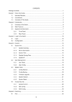
CONTENTS Package Contents ...1 Chapter 1 About this Guide...2 1.1 Intended Readers...2 1.2 Conventions...2 1.3 Overview of This Guide 2 Chapter 2 Introduction...6 2.1 Overview of the Switch 6 2.2 Main Features...6 2.3 Appearance Description 7 2.3.1 Front Panel...7 2.3.2 Rear Panel ...9 Chapter 3 - TP-Link T1500-28PCT TL-SL2428P | T1500-28PCT V1 User Guide - Page 5
5.1.1 Port Config ...32 5.1.2 Port Mirror ...33 5.1.3 Port Security 35 5.1.4 Port Isolation 37 5.1.5 Loopback Detection 38 5.2 LAG ...39 5.2.1 LAG Table...40 5.2.2 Static LAG ...41 5.2.3 LACP Config 42 5.3 Traffic Monitor ...44 5.3.1 Traffic Summary 44 5.3.2 Traffic Statistics 45 5.4 MAC - TP-Link T1500-28PCT TL-SL2428P | T1500-28PCT V1 User Guide - Page 6
110 9.3.2 Port Config 110 9.3.3 OUI Config...111 Chapter 10 PoE ...114 10.1 PoE Config...114 10.1.1 PoE Config 115 10.1.2 PoE Profile 116 10.2 PoE Time-Range...117 10.2.1 Time-Range Summary 117 10.2.2 PoE Time-Range Create 118 10.2.3 PoE Holiday Config 119 Chapter 11 ACL ...120 11.1 ACL Config - TP-Link T1500-28PCT TL-SL2428P | T1500-28PCT V1 User Guide - Page 7
11.1.4 Standard-IP ACL 122 11.1.5 Extend-IP ACL 122 11.1.6 Combined ACL 123 11.2 Policy Config ...124 11.2.1 Policy Summary 124 11.2.2 Policy Create 125 11.2.3 Action Create 125 11.3 Policy Binding ...126 11.3.1 Binding Table 126 11.3.2 Port Binding 127 11.3.3 VLAN Binding 127 11.4 - TP-Link T1500-28PCT TL-SL2428P | T1500-28PCT V1 User Guide - Page 8
Chapter 14Maintenance...161 14.1 System Monitor ...161 14.1.1 CPU Monitor 161 14.1.2 Memory Monitor 162 14.2 Log...162 14.2.1 Log Table...163 14.2.2 Local Log...163 14.2.3 Remote Log 164 14.2.4 Backup Log 165 14.3 Device Diagnostics 166 14.3.1 Cable Test 166 14.4 Network Diagnostics 167 14 - TP-Link T1500-28PCT TL-SL2428P | T1500-28PCT V1 User Guide - Page 9
items should be found in your box: One T1500-28PCT Smart PoE Switch One power cord Two mounting brackets and other fittings Installation Guide Resource CD for T1500-28PCT switch, including: • This User Guide • CLI Reference Guide • SNMP Mibs • Other Helpful Information Note : Make sure - TP-Link T1500-28PCT TL-SL2428P | T1500-28PCT V1 User Guide - Page 10
network managers familiar with IT concepts and network terminologies. 1.2 Conventions In this Guide the following conventions are used: The switch or T1500-28PCT mentioned in this Guide stands for T1500-28PCT Smart PoE Switch without any explanation. Menu Name→Submenu Name→Tab page indicates the - TP-Link T1500-28PCT TL-SL2428P | T1500-28PCT V1 User Guide - Page 11
to enhance the configuration management security. This module is used to configure basic functions of the switch. Here mainly introduces: Port: Configure the basic features for the port. LAG: Configure Link Aggregation Group. LAG is to combine a number of ports together to make a single high - TP-Link T1500-28PCT TL-SL2428P | T1500-28PCT V1 User Guide - Page 12
PoE function for the switch to supply power for PD devices. Here mainly introduces: PoE Config: Configure PoE function globally. PoE Time-Range: Configure the effective time for PoE to provide information for SNMP applications to simplify troubleshooting. Here mainly introduces: Basic Config: - TP-Link T1500-28PCT TL-SL2428P | T1500-28PCT V1 User Guide - Page 13
Chapte r Introduction Appendix A Specifications Lists the hardware specifications of the switch. Appendix B Configure the PCs Introduces how to configure the PCs. Appendix C Glossary Lists the glossary used in this manual. Return to CONTENTS 5 - TP-Link T1500-28PCT TL-SL2428P | T1500-28PCT V1 User Guide - Page 14
Introduction Thanks for choosing the T1500-28PCT Smart PoE Switch! 2.1 Overview of the Switch Designed for workgroups and departments, T1500-28PCT from TP-LINK provides wire-speed performance and full set of layer 2 management features. It provides a variety of service features and multiple powerful - TP-Link T1500-28PCT TL-SL2428P | T1500-28PCT V1 User Guide - Page 15
following parts are located on the front panel of the switch: LEDs T1500-28PCT has an LED mode switch button which is for switching the LED status indication. When the Speed LED is on, the port LED is indicating the data transmission rate. When the PoE LED is on, the port LED is indicating the - TP-Link T1500-28PCT TL-SL2428P | T1500-28PCT V1 User Guide - Page 16
No device is connected to the corresponding port. When the PoE LED is on, the port LED is indicating the power supply status. Name PWR SYS PoE MAX 10/100M or PoE 1000M Status Indication On The switch is powered on. Off The switch is powered off or power supply is abnormal. Flashing Power - TP-Link T1500-28PCT TL-SL2428P | T1500-28PCT V1 User Guide - Page 17
the lock (not provided) into the security slot to prevent the device from being stolen. Grounding Terminal: T1500-28PCT already comes with Lightning Protection Mechanism. You can also ground the switch through the PE (Protecting Earth) cable of AC cord or with the ground cable. AC Power Socket - TP-Link T1500-28PCT TL-SL2428P | T1500-28PCT V1 User Guide - Page 18
IP address of your PC should be set in the same subnet addresses of the switch. The IP address is 192.168.0.x ("x" is any number from 2 to 254), Subnet Mask is 255.255.255.0. For the detailed instructions as to how to do this, please refer to Appendix B. 2) After a moment, a login window - TP-Link T1500-28PCT TL-SL2428P | T1500-28PCT V1 User Guide - Page 19
screen. Figure 3-3 Main Setup-Menu Note : Clicking Apply can only make the new configurations effective before the switch is rebooted. If you want to keep the configurations effective even the switch is rebooted, please click Save Config. You are suggested to click Save Config before cutting off the - TP-Link T1500-28PCT TL-SL2428P | T1500-28PCT V1 User Guide - Page 20
System The System module is mainly for system configuration of the switch, including four submenus: System Info, User M anage, System 24 10/100Mbps RJ45 ports, 4 10/100/1000Mbps RJ45 ports and 2 SFP ports of the switch. Ports 1 to 24 are 10/100Mbps ports. Ports 25-28 are 10/100/1000Mbps ports, - TP-Link T1500-28PCT TL-SL2428P | T1500-28PCT V1 User Guide - Page 21
information of the port will be displayed. Port Info Figure 4-2 Port Information Port: Type : Rate : Status: Displays the port number of the switch. Displays the type of the port. Displays the maximum transmission rate of the port. Displays the connection status of the port. Click a port to - TP-Link T1500-28PCT TL-SL2428P | T1500-28PCT V1 User Guide - Page 22
contact information. 4.1.3 System Time System Time is the time displayed while the switch is running. On this page you can configure the system time and the settings here will be used for other time-based functions. You can manually set the system time or synchronize with PC's clock as the system - TP-Link T1500-28PCT TL-SL2428P | T1500-28PCT V1 User Guide - Page 23
with PC'S Clock: When this option is selected, you can set the date and time manually. When this option is selected, you can configure the time zone and the IP address for the NTP Server. The switch will get UTC automatically if it has connected to an NTP Server. Time Zone: Select - TP-Link T1500-28PCT TL-SL2428P | T1500-28PCT V1 User Guide - Page 24
System IP Each device in the network possesses a unique IP address. You can log on to the Web management page to operate the switch using this IP address. The switch supports three modes to obtain an IP address: Static IP, DHCP and BOOTP. The IP address obtained using a new mode will replace the - TP-Link T1500-28PCT TL-SL2428P | T1500-28PCT V1 User Guide - Page 25
selected, you should enter IP address, Subnet Mask and Default Gateway manually. DHCP: When this option is selected, the switch will obtain network parameters from the DHCP Server. BOOTP: When this option is selected, the switch will obtain network parameters from the BOOTP Server. Enter the ID - TP-Link T1500-28PCT TL-SL2428P | T1500-28PCT V1 User Guide - Page 26
Guest and Admin. The guest only can view the settings without the right to configure the switch; the admin can configure all the functions of the switch. The Web management pages contained in this guide are subject to the admin's login without any explanation. Choose the menu System→User M anagement - TP-Link T1500-28PCT TL-SL2428P | T1500-28PCT V1 User Guide - Page 27
, Firmware Upgrade, System Reboot and System Reset pages. 4.3.1 Config Restore On this page you can upload a backup configuration file to restore your switch to this previous configuration. Choose the menu System→System Tools→Config Restore to load the following page. Figure 4-10 Config Restore 19 - TP-Link T1500-28PCT TL-SL2428P | T1500-28PCT V1 User Guide - Page 28
few minutes to backup the configuration. Please wait without any operation. 4.3.3 Firmware Upgrade The switch system can be upgraded via the Web management page. To upgrade the system is to get more functions and better performance. Go to http://www.tp-link.com to download the updated firmware. 20 - TP-Link T1500-28PCT TL-SL2428P | T1500-28PCT V1 User Guide - Page 29
will reboot automatically. 5. You are suggested to backup the configuration before upgrading. 4.3.4 System Reboot On this page you can reboot the switch and return to the login page. Please save the current configuration before rebooting to avoid losing the configuration unsaved Choose the menu - TP-Link T1500-28PCT TL-SL2428P | T1500-28PCT V1 User Guide - Page 30
the menu System→System Tools→System Reset to load the following page. Figure 4-14 System Reset Note : After the system is reset, the switch will be reset to the default and all the settings will be cleared. 4.4 Access Security Access Security provides different security measures for the remote - TP-Link T1500-28PCT TL-SL2428P | T1500-28PCT V1 User Guide - Page 31
the data transmission between the Web browser and servers. It is mainly applied through ecommerce and online banking. SSL mainly provides the following services: 1. Authenticate the users and the servers based on the certificates to ensure the data are transmitted to the correct users and servers - TP-Link T1500-28PCT TL-SL2428P | T1500-28PCT V1 User Guide - Page 32
, you can log on to the Web management page via https://192.168.0.1. For the first time you use HTTPS connection to log into the switch with the default certificate, you will be prompted that "The security certificate presented by this website was not issued by a trusted certificate authority" or - TP-Link T1500-28PCT TL-SL2428P | T1500-28PCT V1 User Guide - Page 33
, the client sends authentication request to the server for login, and then the two can communicate with each other after successful authentication. This switch supports SSH server and you can log on to the switch via SSH connection using SSH client software. SSH key can be downloaded into the - TP-Link T1500-28PCT TL-SL2428P | T1500-28PCT V1 User Guide - Page 34
when the number of the connections reaches the maximum number you set. The default value is 5. Select the type of SSH key to download. The switch supports three types: SSH-1 RSA, SSH-2 RSA and SSH-2 DSA. Select the desired key file to download. Click the Download button to down the desired key - TP-Link T1500-28PCT TL-SL2428P | T1500-28PCT V1 User Guide - Page 35
Configuration Procedure 1. Open the software to log on to the interface of PuTTY. Enter the IP address of the switch into Host Name field; keep the default value 22 in the Port field; select SSH as the Connection type. 2. Click the Open button in the - TP-Link T1500-28PCT TL-SL2428P | T1500-28PCT V1 User Guide - Page 36
Configuration Procedure 1. Select the key type and key length, and generate SSH key. Note : 1. The key length is in the range of 512 to 3072 bits. 2. During the key generation, randomly moving the mouse quickly can accelerate the key generation. 28 - TP-Link T1500-28PCT TL-SL2428P | T1500-28PCT V1 User Guide - Page 37
successfully generated, please save the public key and private key to the computer. 3. On the Web management page of the switch, download the public key file saved in the computer to the switch. Note : 1. The key type should accord with the type of the key file. 2. The SSH key downloading cannot be - TP-Link T1500-28PCT TL-SL2428P | T1500-28PCT V1 User Guide - Page 38
4. After the public key and private key are downloaded, please log on to the interface of PuTTY and enter the IP address for login. 30 - TP-Link T1500-28PCT TL-SL2428P | T1500-28PCT V1 User Guide - Page 39
private key file to SSH client software and click Open. After successful authentication, please enter the login user name. If you log on to the switch without entering password, it indicates that the key has been successfully downloaded. Return to CONTENTS 31 - TP-Link T1500-28PCT TL-SL2428P | T1500-28PCT V1 User Guide - Page 40
it is in need. The parameters will affect the working mode of the port, please set the parameters appropriate to your needs. Choose the menu Switching→Port→Port Config to load the following page. Figure 5-1Port Config The following entries are displayed on this screen: Port Config Port Select - TP-Link T1500-28PCT TL-SL2428P | T1500-28PCT V1 User Guide - Page 41
this switch does not support auto-negotiation. Allows you to Enable/Disable the Flow Control feature. When Flow Control is enabled, the switch can to analyze the mirrored packets for monitoring and troubleshooting the network. Choose the menu Switching→Port→Port Mirror to load the following page. - TP-Link T1500-28PCT TL-SL2428P | T1500-28PCT V1 User Guide - Page 42
The following entries are displayed on this screen. M irror Group List Group: M irroring: Mode: Mirrored Port: Ope ration: Displays the mirror group number. Displays the mirroring port number. Displays the mirror mode. The value will be "Ingress" or "Egress". Displays the mirrored ports. Click - TP-Link T1500-28PCT TL-SL2428P | T1500-28PCT V1 User Guide - Page 43
the MAC Address Table. When the MAC Address Table is full, the switch will broadcast the packets to all the ports. At this moment, the drop and even breakdown of the system. Port Security is to protect the switch from the malicious MAC Address Attack by limiting the maximum number of MAC addresses - TP-Link T1500-28PCT TL-SL2428P | T1500-28PCT V1 User Guide - Page 44
is selected, the learned MAC address will be out of the influence of the aging time and can only be deleted manually. The learned entries will be cleared after the switch is rebooted. • Permanent: When Permanent mode is selected, the learned MAC address will be out of the influence of the aging - TP-Link T1500-28PCT TL-SL2428P | T1500-28PCT V1 User Guide - Page 45
the network security by forbidding the port to forward packets to the ports that are not on its forward portlist. Choose the menu Switching→Port→Port Isolation to load the following page. Figure 5-5 Port Isolation The following entries are displayed on this screen: Port Isolation Config From - TP-Link T1500-28PCT TL-SL2428P | T1500-28PCT V1 User Guide - Page 46
will display an alert or further block the corresponding port according to the port configuration. Choose the menu Switching→Port→Loopback De tection to load the following page. Figure 5-6 Loopback Detection Config The following entries are displayed on this screen: Global Config Loopback - TP-Link T1500-28PCT TL-SL2428P | T1500-28PCT V1 User Guide - Page 47
for the port. Select the mode how the switch processes the detected loops. • Alert: When a Displays the LAG number the port belongs to. Manually remove the block status of selected ports. Note must coordinate with storm control. 5.2 LAG LAG (Link Aggregation Group) is to combine a number of ports - TP-Link T1500-28PCT TL-SL2428P | T1500-28PCT V1 User Guide - Page 48
bandwidth of each member port is 2000Mbps counting the up-linked speed of 1000Mbps and the down-linked speed of 1000Mbps. 2. The traffic load of the LAG you can view the information of the current LAG of the switch. Choose the menu Switching→LAG→LAG Table to load the following page. Figure 5-7 LAG - TP-Link T1500-28PCT TL-SL2428P | T1500-28PCT V1 User Guide - Page 49
of the LAG. Click the Detail button for the detailed information of your selected LAG. Figure 5-8 Detailed Information 5.2.2 Static LAG On this page, you can manually configure the LAG. Choose the menu Switching→LAG→Static LAG to load the following page. Figure - TP-Link T1500-28PCT TL-SL2428P | T1500-28PCT V1 User Guide - Page 50
Control Protocol) is defined in IEEE802.3ad and enables the dynamic link aggregation and disaggregation by exchanging LACP packets with its partner. The switch can dynamically group similarly configured ports into a single logical link, which will highly extend the bandwidth and flexibly balance the - TP-Link T1500-28PCT TL-SL2428P | T1500-28PCT V1 User Guide - Page 51
Global Config System Priority: Specify the system priority for the switch. The system priority and MAC address constitute the system identification (ID determines which link aggregation a link belongs to, and the system with lower priority adds the proper links to the link aggregation according - TP-Link T1500-28PCT TL-SL2428P | T1500-28PCT V1 User Guide - Page 52
displays the traffic information of each port, which facilitates you to monitor the traffic and analyze the network abnormity. Choose the menu Switching→Traffic Monitor→Traffic Summary to load the following page. Figure 5-11 Traffic Summary The following entries are displayed on this screen: Auto - TP-Link T1500-28PCT TL-SL2428P | T1500-28PCT V1 User Guide - Page 53
Traffic Statistics screen displays the detailed traffic information of each port, which facilitates you to monitor the traffic and locate faults promptly. Choose the menu Switching→Traffic Monitor→Traffic Statistics to load the following page. Figure 5-12 Traffic Statistics 45 - TP-Link T1500-28PCT TL-SL2428P | T1500-28PCT V1 User Guide - Page 54
a port during packet transmissions. 5.4 MAC Address The main function of the switch is forwarding the packets to the correct ports based on the destination MAC address information, which is the base for the switch to forward packets quickly. The entries in the Address Table can be updated - TP-Link T1500-28PCT TL-SL2428P | T1500-28PCT V1 User Guide - Page 55
saved) Static Manually No Yes Address Table configuring Dynamic Automatically Yes No Address Table learning Filtering Manually No Yes can view all the information of the Address Table. Choose the menu Switching→MAC Address→Address Table to load the following page. Figure 5-13 Address - TP-Link T1500-28PCT TL-SL2428P | T1500-28PCT V1 User Guide - Page 56
address table maintains the static address entries which can be added or removed manually, independent of the aging time. In the stable networks, the static MAC address entries can facilitate the switch to reduce broadcast packets and remarkably enhance the efficiency of packets forwarding without - TP-Link T1500-28PCT TL-SL2428P | T1500-28PCT V1 User Guide - Page 57
has been added to the Static Address Table, connecting the device to another port will cause its address not to be recognized dynamically by the switch. Therefore, please ensure the entries in the Static Address Table are correct and valid. 3. The MAC address in the Static Address Table cannot be - TP-Link T1500-28PCT TL-SL2428P | T1500-28PCT V1 User Guide - Page 58
Choose the menu Switching→MAC Address→Dynamic Address to load the following page. Figure 5-15 Dynamic Address The following entries are displayed on this screen: Aging Config Auto Aging: - TP-Link T1500-28PCT TL-SL2428P | T1500-28PCT V1 User Guide - Page 59
address is to forbid the undesired packets to be forwarded. The filtering address can be added or removed manually, independent of the aging time. The filtering MAC address allows the switch to filter the packets which includes this MAC address as the source address or destination address, so as - TP-Link T1500-28PCT TL-SL2428P | T1500-28PCT V1 User Guide - Page 60
is no authentication mechanism between Server and Client. If there are several DHCP servers in the network, network confusion and security problem will happen. To protect the switch from being attacked by illegal DHCP servers, you can configure the desired ports as trusted ports and only the clients - TP-Link T1500-28PCT TL-SL2428P | T1500-28PCT V1 User Guide - Page 61
Figure 5-17 Network diagram of DHCP For different DHCP clients, DHCP server provides three IP address assigning methods: (1) Manually assign the IP address: Allows the administrator to bind the static IP address to a specific client (e.g.: WWW Server) via the DHCP server. (2) Automatically assign - TP-Link T1500-28PCT TL-SL2428P | T1500-28PCT V1 User Guide - Page 62
are several DHCP servers in the network, network confusion and security problem will happen. The common cases incurring the illegal DHCP servers are the following two: (1) It's common that the illegal DHCP server is manually configured by the user by mistake. (2) Hacker exhausted the IP addresses of - TP-Link T1500-28PCT TL-SL2428P | T1500-28PCT V1 User Guide - Page 63
Choose the menu Switching → DHCP Filtering to load the following page. Figure 5-20 DHCP Filtering The following entries are displayed on this screen: DHCP Filtering DHCP Filtering: Enable/Disable - TP-Link T1500-28PCT TL-SL2428P | T1500-28PCT V1 User Guide - Page 64
occupy plenty of bandwidth resources, causing potential serious security problems. A Virtual Local Area Network (VLAN) is a different physical network segments. This switch supports 802.1Q VLAN to classify VLANs. VLAN tags in the packets are necessary for the switch to identify packets of different - TP-Link T1500-28PCT TL-SL2428P | T1500-28PCT V1 User Guide - Page 65
switch to identify packets of different VLANs. The switch works at the data link layer in OSI model and it can identify the data link layer encapsulation of the packet only, so you can add the VLAN tag field into the data link port for transmission. In this User Guide, the tagged packet refers to the - TP-Link T1500-28PCT TL-SL2428P | T1500-28PCT V1 User Guide - Page 66
the port belongs, is an important parameter with the following two purposes: (1) When the switch receives an un-VLAN-tagged packet, it will add a VLAN tag to the packet in different ways, after being received by ports of different link types, which is illustrated in the following table. Port - TP-Link T1500-28PCT TL-SL2428P | T1500-28PCT V1 User Guide - Page 67
Choose the menu VLAN→802.1Q VLAN→VLAN Config to load the following page. Figure 6-3 VLAN Table To ensure the normal communication of the factory switch, the default VLAN of all ports is set to VLAN1. VLAN1 cannot be modified or deleted. The following entries are displayed on this screen: VLAN - TP-Link T1500-28PCT TL-SL2428P | T1500-28PCT V1 User Guide - Page 68
of the specific port. Displays the LAG to which the port belongs to. 6.2 Application Example for 802.1Q VLAN Network Requirements Switch A is connecting to PC A and Server B; Switch B is connecting to PC B and Server A; PC A and Server A is in the same VLAN; PC B and Server B is in the - TP-Link T1500-28PCT TL-SL2428P | T1500-28PCT V1 User Guide - Page 69
create a VLAN with its VLAN ID as 20, owning Port 3 and Port 4. Configure Switch B Ste p 1 2 3 Ope ration De scription Configure the Required. On VLAN→802.1Q VLAN→VLAN Config page, configure Link Type of the the link type of Port 7, Port 6 and Port 8 as Untagged, Tagged and ports Untagged - TP-Link T1500-28PCT TL-SL2428P | T1500-28PCT V1 User Guide - Page 70
to IEEE 802.1D standard, is to disbranch a ring network in the Data Link layer in a local network. Devices running STP discover loops in the network and function, the switches in the network transfer BPDUs between each other to exchange information and all the switches supporting STP receive and - TP-Link T1500-28PCT TL-SL2428P | T1500-28PCT V1 User Guide - Page 71
1 to 10 seconds. It specifies the interval to send BPDU packets. It is used to test the links. Max. Age: Max. Age ranges from 6 to 40 seconds. It specifies the maximum time the switch can wait without receiving a BPDU before attempting to reconfigure. Forward Delay: Forward Delay ranges from 4 to 30 - TP-Link T1500-28PCT TL-SL2428P | T1500-28PCT V1 User Guide - Page 72
is lower than that of the BPDU if of the port itself, the switch discards the BPDU and does not change the BPDU of the port. 2 If designate port The operation is taken in the following way: Step Operation 1 For each switch (except the one chosen as the root bridge) in a network, the port that - TP-Link T1500-28PCT TL-SL2428P | T1500-28PCT V1 User Guide - Page 73
through handshake. RSTP Elements Edge Port: Indicates the port connected directly to terminals. P2P Link: Indicates the link between two switches directly connected. MSTP (Multiple Spanning Tree Protocol), compatible with both STP and RSTP and subject to IEEE 802.1s standard, not only enables - TP-Link T1500-28PCT TL-SL2428P | T1500-28PCT V1 User Guide - Page 74
as STP, MSTP uses BPDUs to generate spanning tree. The only difference is that the BPDU for MSTP carries the MSTP configuration information on the switches. Port States In an MSTP, ports can be in the following four states: Forwarding: In this status the port can receive/forward data, receive - TP-Link T1500-28PCT TL-SL2428P | T1500-28PCT V1 User Guide - Page 75
STP Config, Port Config, M STP Instance and STP Security. 7.1 STP Config The STP Config function, for global configuration of spanning trees on the switch, can be implemented on STP Config and STP Summary pages. 7.1.1 STP Config Before configuring spanning trees, you should make clear the roles each - TP-Link T1500-28PCT TL-SL2428P | T1500-28PCT V1 User Guide - Page 76
regenerating spanning trees frequently and cause network congestions to be falsely regarded as link problems. A too large max age parameter result in the switches unable to find the link problems in time, which in turn handicaps spanning trees being regenerated in time and makes the network less - TP-Link T1500-28PCT TL-SL2428P | T1500-28PCT V1 User Guide - Page 77
7.1.2 STP Summary On this page you can view the related parameters for Spanning Tree function. Choose the menu Spanning Tree→STP Config→STP Summary to load the following page. 7.2 Port Config Figure 7-5 STP Summary On this page you can configure the parameters of the ports for CIST. 69 - TP-Link T1500-28PCT TL-SL2428P | T1500-28PCT V1 User Guide - Page 78
for STP configuration. It is multi-optional. Displays the port number of the switch. Status: Priority: ExtPath: Select Enable /Disable STP function for the desired port forward delay. P2P Link: M Che ck: STP Version: Select the P2P link status. If the two ports in the P2P link are root port or - TP-Link T1500-28PCT TL-SL2428P | T1500-28PCT V1 User Guide - Page 79
Port: Indicates the port that forwards packets to a downstream network segment or switch. Master Port: Indicates the port that connects an MST region to the point links. If the physical link of a port is not a point-to-point link and you forcibly configure the link as a point-to-point link, - TP-Link T1500-28PCT TL-SL2428P | T1500-28PCT V1 User Guide - Page 80
Choose the menu Spanning Tree→MSTP Instance→Region Config to load the following page. Figure 7-7 Region Config The following entries are displayed on this screen: Region Config Region Name: Re v ision: Create a name for MST region identification using up to 32 characters. Enter the revision - TP-Link T1500-28PCT TL-SL2428P | T1500-28PCT V1 User Guide - Page 81
ID for configuration. It is multi-optional. Displays Instance ID of the switch. Displays the status of the instance. Enter the priority of the switch in the instance. It is an important criterion on determining if the switch will be chosen as the root bridge in the specific instance. Enter the - TP-Link T1500-28PCT TL-SL2428P | T1500-28PCT V1 User Guide - Page 82
port number you entered. Select the desired port to specify its priority and path cost. It is multi-optional. Displays the port number of the switch. Enter the priority of the port in the instance. It is an important criterion on determining if the port connected to this port will be - TP-Link T1500-28PCT TL-SL2428P | T1500-28PCT V1 User Guide - Page 83
maintains the states of ports by receiving and processing BPDU packets from the upstream switch. However, when link congestions or link failures occurred to the network, a down stream switch does not receive BPDU packets for certain period, which results in spanning trees being regenerated and - TP-Link T1500-28PCT TL-SL2428P | T1500-28PCT V1 User Guide - Page 84
state and stops forwarding packets (as if it is disconnected from the link). The port resumes the normal state if it does not receive any MSTP provides BPDU protect function. With this function enabled on the switch, the switch shuts down the edge ports that receive BPDUs and reports these - TP-Link T1500-28PCT TL-SL2428P | T1500-28PCT V1 User Guide - Page 85
port for port protect configuration. It is multi-optional. Displays the port number of the switch. Loop Protect is to prevent the loops in the network brought by recalculating STP because of link failures and network congestions. Root Protect is to prevent wrong network topology change caused by - TP-Link T1500-28PCT TL-SL2428P | T1500-28PCT V1 User Guide - Page 86
default value is 5. 7.5 Application Example for STP Function Network Requirements Switch A, B, C, D and E all support MSTP function. A is the central switch. B and C are switches in the convergence layer. D, E and F are switches in the access layer. There are 6 VLANs labeled as VLAN101 - TP-Link T1500-28PCT TL-SL2428P | T1500-28PCT V1 User Guide - Page 87
page, configure the region as TP-LINK and keep the default revision Switch B: Step Operation 1 Configure ports 2 Enable STP function De scription On VLAN→802.1Q VLAN page, configure the link type of the related ports as Tagged, and add the ports to VLAN101-VLAN106. The detailed instructions - TP-Link T1500-28PCT TL-SL2428P | T1500-28PCT V1 User Guide - Page 88
region Config page, configure the region as TP-LINK and keep the default revision setting. 4 Switch D: Step Operation De scription 1 Configure ports On VLAN→802.1Q VLAN page, configure the link type of the related ports as Tagged, and add the ports to VLAN101-VLAN106. The detailed instructions - TP-Link T1500-28PCT TL-SL2428P | T1500-28PCT V1 User Guide - Page 89
2 (VLAN102, 104 and 106), the blue paths in the following figure are connected links; the gray paths are the blocked links. Suggestion for Configuration Enable TC Protect function for all the ports of switches. Enable Root Protect function for all the ports of root bridges. Enable Loop - TP-Link T1500-28PCT TL-SL2428P | T1500-28PCT V1 User Guide - Page 90
users requiring this information is not certain, unicast and broadcast deliver a low efficiency. Multicast solves this problem. It can deliver a high efficiency to send data in the point to multi-point service, which can save large bandwidth and reduce the network load. In multicast, the packets are - TP-Link T1500-28PCT TL-SL2428P | T1500-28PCT V1 User Guide - Page 91
the multicast address table based on the destination multicast address of the multicast packet. If the corresponding entry cannot be found in the table, the switch will broadcast the packet in the VLAN owning the receiving port. If the corresponding entry can be found in the table, it indicates that - TP-Link T1500-28PCT TL-SL2428P | T1500-28PCT V1 User Guide - Page 92
-specific-query message to check if other members in the multicast group of the port need this multicast. When receiving IGMP general query message, the switch will forward them to all other ports in the VLAN owning the receiving port. The receiving port will be processed: if the receiving port is - TP-Link T1500-28PCT TL-SL2428P | T1500-28PCT V1 User Guide - Page 93
host does not send IGMP report message any more, so the switch will remove the port from the corresponding multicast address table when its default value is 300 seconds. Member Port Time: Within the time, if the switch does not receive IGMP report message from the member port, it will consider this - TP-Link T1500-28PCT TL-SL2428P | T1500-28PCT V1 User Guide - Page 94
on this screen: Global Config IGM P Snooping: Unknown Multicast: Select Enable/Disable IGMP Snooping function globally on the switch. Select the operation for the switch to process unknown multicast, Forward or Discard. IGM P Snooping Status De scription: M e mber: Displays IGMP Snooping - TP-Link T1500-28PCT TL-SL2428P | T1500-28PCT V1 User Guide - Page 95
desired port. If Fast Leave is enabled for a port, the switch will immediately remove this port from the multicast group upon receiving IGMP leave Note : 1. Fast Leave on the port is effective only when the host supports IGMPv2 or IGMPv3. 2. When both Fast Leave feature and Unknown Multicast Discard - TP-Link T1500-28PCT TL-SL2428P | T1500-28PCT V1 User Guide - Page 96
consider this port is not a router port any more. Member Port Time: Specify the aging time of the member port. Within this time, if the switch doesn't receive IGMP report message from the member port, it will consider this port is not a member port any more. Leave Time: Specify the interval - TP-Link T1500-28PCT TL-SL2428P | T1500-28PCT V1 User Guide - Page 97
this multicast information and deliver each VLAN owning a receiver one copy. This mode wastes a lot of bandwidth. The problem above can be solved by configuring a multicast VLAN. By adding switch ports to the multicast VLAN and enabling IGMP Snooping, you can make users in different VLANs share the - TP-Link T1500-28PCT TL-SL2428P | T1500-28PCT V1 User Guide - Page 98
Time: Specify the aging time of the member port. Within this time, if the switch doesn't receive IGMP report message from the member port, it will consider this port owning the port on the 802.1Q VLAN page. 3. Configure the link type of the router port in the multicast VLAN as Tagged otherwise all - TP-Link T1500-28PCT TL-SL2428P | T1500-28PCT V1 User Guide - Page 99
in VLAN5. User A: Connected to Port 4 of the switch. User B: Connected to port 5 of the switch. Configure a multicast VLAN, and user A and B pages. For port 3, configure its link type as Tagged, and add it to VLAN3, VLAN4 and VLAN5. For port 4, configure its link type as Untagged, and add it to - TP-Link T1500-28PCT TL-SL2428P | T1500-28PCT V1 User Guide - Page 100
on M ulticast IP Table , Static Multicast IP page. 8.2.1 Multicast IP Table On this page you can view the multicast IP table on the switch. Choose the menu M ulticast→Multicast IP→M ulticast IP Table to load the following page. Figure 8-8 Multicast IP Table The following entries are displayed - TP-Link T1500-28PCT TL-SL2428P | T1500-28PCT V1 User Guide - Page 101
. Displays the type of the multicast IP. Note : If the configuration on VLAN Config page and multicast VLAN page is changed, the switch will clear up the dynamic multicast addresses in multicast address table and learn new addresses. 8.2.2 Static Multicast IP Static Multicast IP table, isolated - TP-Link T1500-28PCT TL-SL2428P | T1500-28PCT V1 User Guide - Page 102
will send IGMP report message. After receiving the report message, the switch will firstly check the multicast filter rules configured for the receiving port table; if the port cannot be added to the multicast group, the switch will drop the IGMP report message. In that way, the multicast streams - TP-Link T1500-28PCT TL-SL2428P | T1500-28PCT V1 User Guide - Page 103
. Take the configuration on this page and the configuration on IP-Range page together to function to implement multicast filter function on the switch. Choose the menu M ulticast→Multicast Filter→Port Filter to load the following page. Figure 8-11 Port Filter The following entries are displayed on - TP-Link T1500-28PCT TL-SL2428P | T1500-28PCT V1 User Guide - Page 104
for ports M ulticast→Multicast Filter→Port Filter page. 8.4 Packet Statistics On this page you can view the multicast data traffic on each port of the switch, which facilitates you to monitor the IGMP messages in the network. 96 - TP-Link T1500-28PCT TL-SL2428P | T1500-28PCT V1 User Guide - Page 105
on the port number you entered. Port: Que ry Packe t: Re port Packe t (V1): Re port Packe t (V2): Displays the port number of the switch. Displays the number of query packets the port received. Displays the number of IGMPv1 report packets the port received. Displays the number of IGMPv2 report - TP-Link T1500-28PCT TL-SL2428P | T1500-28PCT V1 User Guide - Page 106
as to provide a network service experience of a better quality. QoS This switch classifies the ingress packets, When the network is congested, the problem that many packets compete for resources must be solved, usually in the way of queue scheduling. The switch supports four schedule modes: SP, WRR - TP-Link T1500-28PCT TL-SL2428P | T1500-28PCT V1 User Guide - Page 107
switch processes untagged packets based on the default priority mode. 3. DSCP Priority Figure 9-3 IP datagram As shown in the figure above, the ToS (Type of Service , the problem that many packets compete for resources must be solved, usually in the way of queue scheduling. The switch implements four - TP-Link T1500-28PCT TL-SL2428P | T1500-28PCT V1 User Guide - Page 108
value for each queue and every queue can be assured of a certain service time. The weight value indicates the occupied proportion of the resource. WRR TC1 and TC2 is 1:2:4. In this way, when scheduling queues, the switch allows TC3 to occupy the whole bandwidth following the SP mode and the TC0 - TP-Link T1500-28PCT TL-SL2428P | T1500-28PCT V1 User Guide - Page 109
queues and then forwards the packets according to specified scheduling algorithms to implement QoS function. This switch implements three priority modes based on port, on 802.1P and on DSCP, and supports four queue scheduling algorithms. The port priorities are labeled as TC0, TC1, TC2 and TC3. The - TP-Link T1500-28PCT TL-SL2428P | T1500-28PCT V1 User Guide - Page 110
Configuration Procedure: Step Operation 1 Select the port priority 3 Select a schedule mode De scription Required. On QoS→DiffServ→Port Priority page, configure the port priority. Required. On QoS→DiffServ→Schedule Mode page, select a schedule mode. 9.1.2 802.1P/CoS Mapping On this page you - TP-Link T1500-28PCT TL-SL2428P | T1500-28PCT V1 User Guide - Page 111
Configuration Procedure: Step Operation De scription 1 Log on to the 802.1P/CoS Mapping page 2 Enable 802.1P priority Required. By default, the 802.1P priority function is function disabled. 3 Map the 802.1P priority tag to Required. Select 802.1P priority tag and the the priority level - TP-Link T1500-28PCT TL-SL2428P | T1500-28PCT V1 User Guide - Page 112
mode Required. Log on to the Schedule Mode page to select a schedule mode. 9.1.4 Schedule Mode On this page you can select a schedule mode for the switch. When the network is congested, the problem that many packets compete for resources must be solved, usually in the way of queue scheduling. The - TP-Link T1500-28PCT TL-SL2428P | T1500-28PCT V1 User Guide - Page 113
Strict-Priority + Weight Round Robin Mode. In this mode, this switch provides two scheduling groups, SP group and WRR group. Queues in ratio of TC0, TC1 and TC2 is 1:2:4. In this way, when scheduling queues, the switch allows TC3 to occupy the whole bandwidth following the SP mode and the TC0, TC1 - TP-Link T1500-28PCT TL-SL2428P | T1500-28PCT V1 User Guide - Page 114
port for Rate configuration. It is multi-optional. Displays the port number of the switch. Configure the bandwidth for receiving packets on the port. You can select a rate from the dropdown list or select "Manual" to set Ingress rate, the system will automatically select integral multiple of 64Kbps - TP-Link T1500-28PCT TL-SL2428P | T1500-28PCT V1 User Guide - Page 115
entered. Se le ct: Select the desired port for Storm Control configuration. It is multi-optional. Port: Displays the port number of the switch. Broadcast (bps): Mulitcast (bps): UL-Frame (bps): LAG: Rate Rate Rate Select the bandwidth for receiving broadcast packets on the port. The packet - TP-Link T1500-28PCT TL-SL2428P | T1500-28PCT V1 User Guide - Page 116
remove this port from voice VLAN. Voice ports are automatically added into or removed from voice VLAN. Manual Mode: You need to manually add the port of IP phone to voice VLAN, and then the switch will assign ACL rules and configure the priority of the packets through learning the source MAC address - TP-Link T1500-28PCT TL-SL2428P | T1500-28PCT V1 User Guide - Page 117
VLAN Mode Voice Stream Type Link type of the port and processing mode TAG voice stream Automatic Mode Untagged: Not supported. Tagged: Supported. The default VLAN of the port cannot be voice VLAN. UNTAG voice Untagged: Supported. stream Tagged: Not supported. Manual Mode TAG voice stream - TP-Link T1500-28PCT TL-SL2428P | T1500-28PCT V1 User Guide - Page 118
9.3.1 Global Config On this page, you can configure the global parameters of the voice VLAN, including VLAN ID and aging time. Choose the menu QoS→Voice VLAN→Global Config to load the following page. Figure 9-12 Global Configuration The following entries are displayed on this screen: Global - TP-Link T1500-28PCT TL-SL2428P | T1500-28PCT V1 User Guide - Page 119
switch automatically adds a port to the voice VLAN or removes a port from the voice VLAN by checking whether the port receives voice data or not. Manual: In this mode, you can manually to. 9.3.3 OUI Config The switch supports OUI creation and adds the MAC address of the special voice device to the - TP-Link T1500-28PCT TL-SL2428P | T1500-28PCT V1 User Guide - Page 120
VLAN: Step Operation 1 Configure the link type of the port 2 Create VLAN link type of ports of the voice device. Required. On VLAN→802.1Q VLAN→VLAN Config page, click the Create button to create a VLAN. Optional. On QoS→Voice VLAN→OUI Config page, you can check whether the switch is supporting - TP-Link T1500-28PCT TL-SL2428P | T1500-28PCT V1 User Guide - Page 121
Step Operation 4 Configure the parameters of the ports in voice VLAN. 5 Enable Voice VLAN De scription Required. On QoS→Voice VLAN→Port Config page, configure the parameters of the ports in voice VLAN. Required. On QoS→Voice VLAN→Global Config page, configure the global parameters of voice - TP-Link T1500-28PCT TL-SL2428P | T1500-28PCT V1 User Guide - Page 122
T1500-28PCT is a Power Sourcing Equipment (PSE). All the Auto-Negotiation RJ45 ports on the switch support Power over Ethernet (PoE) linked PDs. When the power exceeds the maximum power limit or the power is inadequate to power the device, the switch may disconnect the power supply to the PD linked - TP-Link T1500-28PCT TL-SL2428P | T1500-28PCT V1 User Guide - Page 123
the parameters to implement PoE function. Choose the menu PoE→PoE Config→PoE Config to load the following page. Figure 10-1 PoE Config for T1500-28PCT The following items are displayed on this screen: Global Config System Power Limit: Specify the max power the PoE switch can supply. Syste - TP-Link T1500-28PCT TL-SL2428P | T1500-28PCT V1 User Guide - Page 124
power exceeds the system power limit, the PD linked to the port with lower priority will be disconnected. Power Limit: Defines the max power the corresponding port can supply. Class1 represents 4w, Class2 represents 7w, Class3 represents 15.4w, and Class4 represents 30w. (for T1500-28PCT) 116 - TP-Link T1500-28PCT TL-SL2428P | T1500-28PCT V1 User Guide - Page 125
A time-range based PoE enables you to implement PoE power supply by differentiating the time-ranges. A time-range can be specified for each port. The port will not supply power when the specified time-range is configured and the system time is not within the time-range. On this switch absolute time - TP-Link T1500-28PCT TL-SL2428P | T1500-28PCT V1 User Guide - Page 126
Time-Range Create On this page you can create time-ranges. Choose the menu PoE→PoE Time-Range→PoE Time-Range Create to load the following page. Figure 10-4 Time-Range Create Note : To successfully configure time-ranges, please firstly specify time-slices and - TP-Link T1500-28PCT TL-SL2428P | T1500-28PCT V1 User Guide - Page 127
access control policy from the week mode. On this page you can define holidays according to your work arrangement. Choose the menu PoE→PoE Time -Range →PoE Holiday Cre ate to load the following page. Figure 10-5 Holiday Configuration The following entries are displayed on this screen: Create - TP-Link T1500-28PCT TL-SL2428P | T1500-28PCT V1 User Guide - Page 128
without considering the other rules, which can enhance the performance of the switch. The ACL Config function can be implemented on ACL Summary, ACL Summary On this page, you can view the current ACLs configured in the switch. Choose the menu ACL→ACL Config→ACL Summary to load the following page. - TP-Link T1500-28PCT TL-SL2428P | T1500-28PCT V1 User Guide - Page 129
ACL ACL ID: Select the desired MAC ACL for configuration. Rule ID: Enter the rule ID. Ope ration: S-M AC: Select the operation for the switch to process packets which match the rules. Permit: Forward packets. Deny: Discard Packets. Enter the source MAC address contained in the rule. 121 - TP-Link T1500-28PCT TL-SL2428P | T1500-28PCT V1 User Guide - Page 130
ACL ID: Rule ID: Select the desired Standard-IP ACL for configuration. Enter the rule ID. Ope ration: S-IP: Select the operation for the switch to process packets which match the rules. Permit: Forward packets. Deny: Discard Packets. Enter the source IP address contained in the rule. D-IP - TP-Link T1500-28PCT TL-SL2428P | T1500-28PCT V1 User Guide - Page 131
ACL ID: Select the desired Extend-IP ACL for configuration. Rule ID: Enter the rule ID. Ope ration: S-IP: Select the operation for the switch to process packets which match the rules. Permit: Forward packets. Deny: Discard Packets. Enter the source IP address contained in the rule. D-IP - TP-Link T1500-28PCT TL-SL2428P | T1500-28PCT V1 User Guide - Page 132
Rule ACL ID: Select the desired Combined ACL for configuration. Rule ID: Enter the rule ID. Ope ration: S-M AC: Select the operation for the switch to process packets which match the rules. Permit: Forward packets. Deny: Discard Packets. Enter the source MAC address contained in the rule - TP-Link T1500-28PCT TL-SL2428P | T1500-28PCT V1 User Guide - Page 133
Choose the menu ACL→Policy Config→Policy Summary to load the following page. Figure 11-7 Policy Summary The following entries are displayed on this screen: Search Option Select Policy: Action Table Select name of the desired policy for view. If you want to delete the desired policy, please - TP-Link T1500-28PCT TL-SL2428P | T1500-28PCT V1 User Guide - Page 134
Choose the menu ACL→Policy Config→Action Create to load the following page. Figure 11-9 Action Create The following entries are displayed on this screen: Create Action Select Policy: Select the name of the policy. Se le ct ACL: Select the ACL for configuration in the policy. 11.3 Policy - TP-Link T1500-28PCT TL-SL2428P | T1500-28PCT V1 User Guide - Page 135
Inde x: Policy Name: Inte rface: Dire ction: Displays the index of the binding policy. Displays the name of the binding policy. Displays the port number or VLAN ID bound to the policy. Displays the binding direction. 11.3.2 Port Binding On this page you can bind a policy to a port. Choose the menu - TP-Link T1500-28PCT TL-SL2428P | T1500-28PCT V1 User Guide - Page 136
Choose the menu ACL→Policy Binding→VLAN Binding to load the following page. Figure 11-12 Bind the policy to the VLAN The following entries are displayed on this screen: VLAN-Bind Config Policy Name: Select the name of the policy you want to bind. VLAN ID: Enter the ID of the VLAN you want to - TP-Link T1500-28PCT TL-SL2428P | T1500-28PCT V1 User Guide - Page 137
Network Diagram Configuration Procedure Step Operation De scription 1 Configure for On ACL→ACL Config→ACL Cre ate page, create ACL 11. requirement 1 On ACL→ACL Config→MAC ACL page, select ACL 11, create Rule 1, configure the operation as Permit, configure the S-MAC as 00-46-A5-5D-12-C3 and - TP-Link T1500-28PCT TL-SL2428P | T1500-28PCT V1 User Guide - Page 138
Step Operation De scription 3 Configure for On ACL→ACL Config→ACL Cre ate page, create ACL 101. requirement 3 On ACL→ACL Config→Standard-IP ACL page, select ACL 101, and 4 create Rule 4, configure operation as Deny, configure S-IP as 10.10.50.0 and mask as 255.255.255.0, configure D-IP as 10. - TP-Link T1500-28PCT TL-SL2428P | T1500-28PCT V1 User Guide - Page 139
Management Station, SNMP Agent and MIB is illustrated in the following figure. Figure 12-1 Relationship among SNMP Network Elements SNM P Versions This switch supports SNMP v3, and is compatible with SNMP v1 and SNMP v2c. The SNMP versions adopted by SNMP Management Station and SNMP Agent should - TP-Link T1500-28PCT TL-SL2428P | T1500-28PCT V1 User Guide - Page 140
SNMP v1: SNMP v1 adopts Community Name authentication. The community name is used to define the relation between SNMP Management Station and SNMP Agent. The SNMP packets failing to pass community name authentication are discarded. The community name can limit access to SNMP Agent from SNMP NMS, - TP-Link T1500-28PCT TL-SL2428P | T1500-28PCT V1 User Guide - Page 141
for SNMP Management Station to access the SNMP Agent, functioning as the password. SNMP module is used to configure the SNMP function of the switch, including three submenus: SNM P Config, Notification and RM ON. 12.1 SNMP Config The SNMP Config can be implemented on the Global Config, SNMP View - TP-Link T1500-28PCT TL-SL2428P | T1500-28PCT V1 User Guide - Page 142
ID characters must be even. 12.1.2 SNMP View The OID (Object Identifier) of the SNMP packets is used to describe the managed objects of the switch, and the MIB (Management Information Base) is the set of the OIDs. The SNMP View is created for the SNMP management station to manage MIB - TP-Link T1500-28PCT TL-SL2428P | T1500-28PCT V1 User Guide - Page 143
12.1.3 SNMP Group On this page, you can configure SNMP Group to control the network access by providing the users in various groups with different management rights via the Read View, Write View and Notify View. Choose the menu SNM P→SNM P Config→SNM P Group to load the following page. Figure 12-5 - TP-Link T1500-28PCT TL-SL2428P | T1500-28PCT V1 User Guide - Page 144
can receive trap messages of the assigned SNMP view generated by the switch's SNMP agent. Select the desired entry to delete the corresponding group viewDefault. 12.1.4 SNMP User The User in an SNMP Group can manage the switch via the management station software. The User and its Group have the same - TP-Link T1500-28PCT TL-SL2428P | T1500-28PCT V1 User Guide - Page 145
The following entries are displayed on this screen: User Config User Name: User Type: Group Name: Security Model: Se curity Le v el: Auth Mode: Auth Password: Privacy Mode: Priv acy Password: Enter the User Name here. Select the type for the User. • Local User: Indicates that the user is - TP-Link T1500-28PCT TL-SL2428P | T1500-28PCT V1 User Guide - Page 146
12.1.5 SNMP Community SNMP v1 and SNMP v2c adopt community name authentication. The community name can limit access to the SNMP agent from SNMP network management station, functioning as a password. If SNMP v1 or SNMP v2c is employed, you can directly configure the SNMP Community on this page - TP-Link T1500-28PCT TL-SL2428P | T1500-28PCT V1 User Guide - Page 147
Configuration Procedure: If SNMPv3 is employed, please take the following steps: Step Operation 1 Enable SNM P function globally. 2 Create SNMP View. 3 Create SNMP Group. 4 Create SNMP User. De scription Required. On the SNMP→SNMP Config→Global Config page, enable SNMP function globally. - TP-Link T1500-28PCT TL-SL2428P | T1500-28PCT V1 User Guide - Page 148
.2 Notification With the Notification function enabled, the switch can initiatively report to the management station about Inform packet is sent to inform the management station and ask for the reply. The switch will resend the inform request if it doesn't get the response from the management - TP-Link T1500-28PCT TL-SL2428P | T1500-28PCT V1 User Guide - Page 149
times reach the specified Re try times. Specify the maximum time for the switch to wait for the response from the management station before resending a request. management station and managed agent. RMON Group This switch supports the following four RMON Groups defined on the RMON standard - TP-Link T1500-28PCT TL-SL2428P | T1500-28PCT V1 User Guide - Page 150
Group Function After a history group is configured, the switch collects and records network statistics information periodically, based on monitored variable exceeds the threshold, an alarm event is generated, which triggers the switch to act in the set way. The RMON Groups can be configured on - TP-Link T1500-28PCT TL-SL2428P | T1500-28PCT V1 User Guide - Page 151
12.3.2 Event Config On this page, you can configure the RMON events. Choose the menu SNM P→RM ON→Event Config to load the following page. Figure 12-10 Event Config The following entries are displayed on this screen: Event Table Se le ct: Inde x: Use r: De scription: Type : Owne r: Status: - TP-Link T1500-28PCT TL-SL2428P | T1500-28PCT V1 User Guide - Page 152
Choose the menu SNM P→RM ON→Alarm Config to load the following page. Figure 12-11 Alarm Config The following entries are displayed on this screen: Alarm Table Se le ct: Inde x: Variable : Select the desired entry for configuration. Displays the index number of the entry. Select the alarm - TP-Link T1500-28PCT TL-SL2428P | T1500-28PCT V1 User Guide - Page 153
Inte rval: Owne r: Status: Enter the alarm interval time in seconds. Enter the name of the device or user that defined the entry. Select Enable/Disable the corresponding alarm entry. Note : When alarm variables exceed the Threshold on the same direction continuously for several times, an alarm - TP-Link T1500-28PCT TL-SL2428P | T1500-28PCT V1 User Guide - Page 154
and these TLVs are encapsulated in LLDPDU (Link Layer Discovery Protocol Data Unit). The LLDPDU as Voice over IP phones and network switches. The LLDP-MED TLVs advertise information such by SNMP applications to simplify troubleshooting, enhance network management, and supported by each port. 146 - TP-Link T1500-28PCT TL-SL2428P | T1500-28PCT V1 User Guide - Page 155
Tx&Rx: the port can both transmit and receive LLDPDUs. Rx_Only: the port can receive LLDPDUs only. Tx_Only: the port can transmit LLDPDUs only. Disable: the port cannot transmit or receive LLDPDUs. 2) LLDPDU transmission mechanism If the ports are working in TxRx or Tx mode, they will - TP-Link T1500-28PCT TL-SL2428P | T1500-28PCT V1 User Guide - Page 156
VLAN ID TLV, VLAN Name TLV And Protocol Identity TLV are defined by IEEE 802.1, while MAC/PHY Configuration/Status TLV, Power Via MDI TLV, Link Aggregation TLV and Maximum Frame TLV are defined by IEEE 802.3. Some specific TLVs are for LLDP-MED protocol, such as LLDP-MED Capabilities TLV - TP-Link T1500-28PCT TL-SL2428P | T1500-28PCT V1 User Guide - Page 157
.1AB standard and ANSI/TIA-1057. In TP-LINK switch, the following LLDP optional TLVs are supported. TLV Type De scription Port Description TLV c)Whether these settings are the result of auto-negotiation during link initiation or of manual set override action. Max Frame Size TLV The Maximum Frame - TP-Link T1500-28PCT TL-SL2428P | T1500-28PCT V1 User Guide - Page 158
The LLDP module is mainly for LLDP function configuration of the switch, including three submenus: Basic Config, Device Info, Device Statistics and LLDP-MED. 13.1 Basic Config LLDP is configured on the Global Config and Port Config - TP-Link T1500-28PCT TL-SL2428P | T1500-28PCT V1 User Guide - Page 159
Fast Start Times: When the port's LLDP state transforms from Disable (or Rx_Only) to Tx&Rx (or Tx_Only), the fast start mechanism will be enabled, that is, the transmit interval will be shorten to a second, and several LLDPDUs will be sent out (the number of LLDPDUs equals this parameter). The - TP-Link T1500-28PCT TL-SL2428P | T1500-28PCT V1 User Guide - Page 160
13.2 Device Info You can view the LLDP information of the local device and its neighbors on the Local Info and Neighbor Info pages respectively. 13.2.1 Local Info On this page you can see all ports' configuration and system information. Choose the menu LLDP→Device Info→Local Info to load the - TP-Link T1500-28PCT TL-SL2428P | T1500-28PCT V1 User Guide - Page 161
device. Displays the Chassis ID of the neighbor device. Displays the system description of the neighbor device. Displays the port number of the neighbor linking to local port. Click Information to display the detailed information of the neighbor device. 13.3 Device Statistics You can view the LLDP - TP-Link T1500-28PCT TL-SL2428P | T1500-28PCT V1 User Guide - Page 162
Choose the menu LLDP→Device Statistics→Statistic Info to load the following page. Figure 13-5 LLDP Statistic Information The following entries are displayed on this screen: Auto Refresh Auto Refresh: Enable/Disable the auto refresh function. Refresh Rate: Specify the auto refresh rate. - TP-Link T1500-28PCT TL-SL2428P | T1500-28PCT V1 User Guide - Page 163
the number of overtime neighbors linking to this port. Displays IP phones and network switches. The LLDP-MED TLVs aspects of IP communications service, based on IEEE 802 supports media stream capabilities. Communication Device Endpoint (Class III): The class of Endpoint Device that directly supports - TP-Link T1500-28PCT TL-SL2428P | T1500-28PCT V1 User Guide - Page 164
, Software Revision TLV, Serial Number TLV, Manufacturer Name TLV, Model Name TLV and Asset ID TLV. If support for any of the TLVs in the Inventory Management set is implemented, then support for all Inventory Management TLVs shall be implemented. LLDP-MED is configured on the Global Config, Port - TP-Link T1500-28PCT TL-SL2428P | T1500-28PCT V1 User Guide - Page 165
13.4.2 Port Config On this page you can configure all ports' LLDP-MED parameters. Choose the menu LLDP→LLDP-MED→Port Config to load the following page. Figure 13-7 LLDP-MED Port Configuration The following entries are displayed on this screen: LLDP-MED Port Config Port Select: LLDP-MED Status: - TP-Link T1500-28PCT TL-SL2428P | T1500-28PCT V1 User Guide - Page 166
the Location Identification TLV's content in outgoing LLDPDU of the port. Eme rgency Numbe r: Civ ic Addre ss: Emergency number is Emergency Call Service ELIN identifier, which is used during emergency call setup to a traditional CAMA or ISDN trunk-based PSAP. The Civic address is defined to - TP-Link T1500-28PCT TL-SL2428P | T1500-28PCT V1 User Guide - Page 167
Choose the menu LLDP→LLDP-MED→Local Info to load the following page. Figure 13-8 LLDP-MED Local Information The following entries are displayed on this screen: Auto Refresh Auto Refresh: Enable/Disable the auto refresh function. Refresh Rate: Specify the auto refresh rate. Local Info - TP-Link T1500-28PCT TL-SL2428P | T1500-28PCT V1 User Guide - Page 168
Choose the menu LLDP→LLDP-MED→Neighbor Info to load the following page. Figure 13-9 LLDP-MED Neighbor Information The following entries are displayed on this screen: Auto Refresh Auto Refresh: Enable/Disable the auto refresh function. Refresh Rate: Specify the auto refresh rate. Neighbor - TP-Link T1500-28PCT TL-SL2428P | T1500-28PCT V1 User Guide - Page 169
, provides the convenient method to locate and solve the network problem. (1) System Monitor: Monitor the utilization status of the memory and the CPU of switch. (2) Log: View the configuration parameters of the switch and find out the errors via the Logs. (3) Device Diagnostics: Test the connection - TP-Link T1500-28PCT TL-SL2428P | T1500-28PCT V1 User Guide - Page 170
can record, classify and manage the system information effectively, providing powerful support for network administrator to monitor network operation and diagnose malfunction. The Logs of switch are classified into the following eight levels. Severity emergencies alerts critical errors warnings - TP-Link T1500-28PCT TL-SL2428P | T1500-28PCT V1 User Guide - Page 171
the Log Table, Local Log, Remote Log and Backup Log pages. 14.2.1 Log Table The switch supports logs output to two directions, namely, log buffer and log file. The information in log buffer will be lost after the switch is rebooted or powered off whereas the information in log file will be kept - TP-Link T1500-28PCT TL-SL2428P | T1500-28PCT V1 User Guide - Page 172
with the same or smaller severity level value will be output. Status: Enable/Disable the channel. 14.2.3 Remote Log Remote log feature enables the switch to send system logs to the Log Server. Log Server is to centralize the system logs from various devices for the administrator to monitor and - TP-Link T1500-28PCT TL-SL2428P | T1500-28PCT V1 User Guide - Page 173
page. Figure 14-5 Log Host The following entries are displayed on this screen: Log Host Inde x: Displays the index of the log host. The switch supports 4 log hosts. Host IP: Configure the IP for the log host. UDP Port: Displays the UDP port used for receiving/sending log information. Here - TP-Link T1500-28PCT TL-SL2428P | T1500-28PCT V1 User Guide - Page 174
device diagnostics. 14.3.1 Cable Test Cable Test functions to test the connection status of the cable connected to the switch, which facilitates you to locate and diagnose the trouble spot of the network. Choose the menu Maintenance→Device Diagnostics→Cable Test to load the following page. Figure - TP-Link T1500-28PCT TL-SL2428P | T1500-28PCT V1 User Guide - Page 175
reference. 4. If the port is 100Mbps and its connection status is normal, cable test can't get the length of the cable. 14.4 Network Diagnostics This switch provides Ping test and Tracert test functions for network diagnostics. 14.4.1 Ping Ping test function, testing the connectivity between the - TP-Link T1500-28PCT TL-SL2428P | T1500-28PCT V1 User Guide - Page 176
of the gateways during its journey from the source to destination of the test data. When malfunctions occur to the network, you can locate trouble spot of the network with this tracert test. Choose the menu Maintenance→Network Diagnostics→Tracert to load the following page. Figure 14-10 Tracert - TP-Link T1500-28PCT TL-SL2428P | T1500-28PCT V1 User Guide - Page 177
) 1000Base-T: 4-pair UTP (≤100m) of Cat. 5e or above 1000Base-X: MMF or SMF SFP Module (Optional) LED PWR, SYS, PoE MAX, FAN, 10/100M or PoE, 1000M LEDs, 1000Mbps LEDs Transmission Method Store and Forward Packets Forwarding Rate 10BASE-T:14881pps/port 100BASE-TX:148810pps/port 1000Base - TP-Link T1500-28PCT TL-SL2428P | T1500-28PCT V1 User Guide - Page 178
introduce how to install and configure the TCP/IP correctly in Windows 7. First make sure your Ethernet Adapter is working, refer to the adapter's manual if necessary. Configure TCP/IP component 1) On the Windows taskbar, click the Start button, and then click Control Panel. 2) Click the Network and - TP-Link T1500-28PCT TL-SL2428P | T1500-28PCT V1 User Guide - Page 179
4) Double click the Local Network icon in the prompt window. 5) Double click on the Internet Protocol Version 4 (TCP/IPv4) in the Local Network Properties window. Figure B-0-2 171 - TP-Link T1500-28PCT TL-SL2428P | T1500-28PCT V1 User Guide - Page 180
General tab is open on this window by default. Figure B-0-3 7) Select Use the following IP address. And the following items will be available. If the switch's IP address is 192.168.0.1, specify IP address as 192.168.0.x (x is from 2 to 254), and the Subnet mask as 255.255.255.0. Now: Click - TP-Link T1500-28PCT TL-SL2428P | T1500-28PCT V1 User Guide - Page 181
TFTP server that contains the devices system files, and the name of the boot file. Class of Service (CoS) CoS is supported by prioritizing packets based on the required level of service, and then placing them in the appropriate output queue. Data is transmitted from the queues using weighted round - TP-Link T1500-28PCT TL-SL2428P | T1500-28PCT V1 User Guide - Page 182
switch filters incoming multicast frames for services forwhich no attached host has registered, or forwards them to all ports contained within the designated multicast group. Layer 2 Data Link target port is mirrored to a monitor port for troubleshooting with a logic analyzer or RMON probe. This - TP-Link T1500-28PCT TL-SL2428P | T1500-28PCT V1 User Guide - Page 183
any loops. A loop can often occur in complicated or backup linked network systems. Spanning Tree detects and directs data along the shortest datagram mode for packet-switched communications. It uses IP as the underlying transport mechanism to provide access to IP-like services. UDP packets are
-
 1
1 -
 2
2 -
 3
3 -
 4
4 -
 5
5 -
 6
6 -
 7
7 -
8
-
9
-
10
-
11
-
12
-
13
-
14
-
15
-
16
-
17
-
18
-
19
-
20
-
21
-
22
-
23
-
24
-
25
-
26
-
27
-
28
-
29
-
30
-
31
-
32
-
33
-
34
-
35
-
36
-
37
-
38
-
39
-
40
-
41
-
42
-
43
-
44
-
45
-
46
-
47
-
48
-
49
-
50
-
51
-
52
-
53
-
54
-
55
-
56
-
57
-
58
-
59
-
60
-
61
-
62
-
63
-
64
-
65
-
66
-
67
-
68
-
69
-
70
-
71
-
72
-
73
-
74
-
75
-
76
-
77
-
78
-
79
-
80
-
81
-
82
-
83
-
84
-
85
-
86
-
87
-
88
-
89
-
90
-
91
-
92
-
93
-
94
-
95
-
96
-
97
-
98
-
99
-
100
-
101
-
102
-
103
-
104
-
105
-
106
-
107
-
108
-
109
-
110
-
111
-
112
-
113
-
114
-
115
-
116
-
117
-
118
-
119
-
120
-
121
-
122
-
123
-
124
-
125
-
126
-
127
-
128
-
129
-
130
-
131
-
132
-
133
-
134
-
135
-
136
-
137
-
138
-
139
-
140
-
141
-
142
-
143
-
144
-
145
-
146
-
147
-
148
-
149
-
150
-
151
-
152
-
153
-
154
-
155
-
156
-
157
-
158
-
159
-
160
-
161
-
162
-
163
-
164
-
165
-
166
-
167
-
168
-
169
-
170
-
171
-
172
-
173
-
174
-
175
-
176
-
177
-
178
-
179
-
180
-
181
-
182
-
183
 |
 |

T1500-28PCT
Smart PoE Switch
REV1.0.0
1910011254