TP-Link TD-VG3631 TD-VG3631 V1 User Guide - Page 13
Panel Layout, 1.3.1 The Front Panel - modem
 |
View all TP-Link TD-VG3631 manuals
Add to My Manuals
Save this manual to your list of manuals |
Page 13 highlights
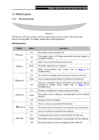
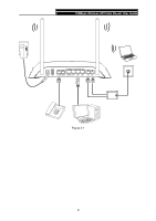
1.3 Panel Layout 1.3.1 The Front Panel 150Mbps Wireless AP/Client Router User Guide Figure 1-1 The Router's LEDs are located on the front panel (View from left to right). They indicate the device's working status. For details, please refer to LED Explanation. LED Explanation: Name (Power) (ADSL) (Internet) (WLAN) (LAN1-4) (USB) Status On Off On Flash Off On Flash Off On Flash Off On Flash Off On Flash Off Indication The modem router is powered on. The modem router is off. Please ensure that the power adapter is connected correctly. ADSL line is synchronized and ready to use. The ADSL negotiation is in progress. ADSL synchronization fails. Please refer to Note 1 for troubleshooting. The network is available with a successful Internet connection. There is data being transmitted or received via the Internet. There is no successful Internet connection or the modem router is operating in Bridge mode. Please refer to Note 2 for troubleshooting. Wireless is enabled but no data is being transmitted. The modem router is sending or receiving data over the wireless network. Wireless function is disabled. There is a device connected to this LAN port. The modem router is sending or receiving data over this LAN port. There is no device connected to this LAN port. A storage device or printer has connected to the USB port. The modem router is sending or receiving data over this USB port. No storage device or printer is plugged into the USB port. 4
-
 1
1 -
2
-
3
-
4
-
5
-
6
-
7
-
 8
8 -
 9
9 -
 10
10 -
 11
11 -
 12
12 -
 13
13 -
 14
14 -
 15
15 -
 16
16 -
 17
17 -
 18
18 -
19
-
20
-
21
-
22
-
23
-
24
-
25
-
26
-
27
-
28
-
29
-
30
-
31
-
32
-
33
-
34
-
35
-
36
-
37
-
38
-
39
-
40
-
41
-
42
-
43
-
44
-
45
-
46
-
47
-
48
-
49
-
50
-
51
-
52
-
53
-
54
-
55
-
56
-
57
-
58
-
59
-
60
-
61
-
62
-
63
-
64
-
65
-
66
-
67
-
68
-
69
-
70
-
71
-
72
-
73
-
74
-
75
-
76
-
77
-
78
-
79
-
80
-
81
-
82
-
83
-
84
-
85
-
86
-
87
-
88
-
89
-
90
-
91
-
92
-
93
-
94
-
95
-
96
-
97
-
98
-
99
-
100
-
101
-
102
-
103
-
104
-
105
-
106
-
107
-
108
-
109
-
110
-
111
-
112
-
113
-
114
-
115
-
116
-
117
-
118
-
119
-
120
-
121
-
122
-
123
-
124
-
125
 |
 |
