TP-Link TL-SL3428 User Guide - Page 27
Connecting the Device, 3.3.1 Connecting the Switch to a Terminal
 |
UPC - 845973020491
View all TP-Link TL-SL3428 manuals
Add to My Manuals
Save this manual to your list of manuals |
Page 27 highlights
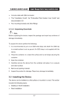
TL-SG3109/TL-SL3428/TL-SL3452 Gigabit Managed Switch Family Installation Guide 5. Secure the unit to the rack with the rack screws (not provided). Fasten the lower pair of screws before the upper pair of screws. This ensures that the weight of the unit is evenly distributed during installation. Ensure that the ventilation holes are not obstructed. 3.3 Connecting the Device This section describes how to connect the device, and includes the following sections: Connecting the Switch to a Terminal AC Power Connection 3.3.1 Connecting the Switch to a Terminal The device is connected to a terminal through an console port on the front panel, which enables a connection to a terminal desktop system running terminal emulation software for monitoring and configuring the device. The terminal must be a VT100 compatible terminal or a desktop or portable system with a serial port and running VT100 terminal emulation software. To connect a terminal to the device Console port, perform the following: 1. Connect a cable to the terminal running VT100 terminal emulation software. 2. Ensure that the terminal emulation software is set as follows: a) Select the appropriate port to connect to the device. b) Set the data rate to 38400 baud. c) Set the data format to 8 data bits, 1 stop bit, and no parity. d) Set flow control to none. e) Under Properties, select VT100 for Emulation mode. f) Select Terminal keys for Function, Arrow and Ctrl keys. Ensure that the 20
-
 1
1 -
2
-
3
-
4
-
5
-
6
-
7
-
8
-
9
-
10
-
11
-
12
-
13
-
14
-
15
-
16
-
17
-
18
-
19
-
20
-
21
-
 22
22 -
 23
23 -
 24
24 -
 25
25 -
 26
26 -
 27
27 -
 28
28 -
 29
29 -
 30
30 -
 31
31 -
 32
32 -
33
-
34
-
35
-
36
-
37
-
38
-
39
-
40
-
41
-
42
-
43
-
44
-
45
-
46
-
47
-
48
-
49
-
50
-
51
-
52
-
53
-
54
 |
 |
