Thermador T36BT820NS Installation Manual
Thermador T36BT820NS Manual
 |
View all Thermador T36BT820NS manuals
Add to My Manuals
Save this manual to your list of manuals |
Thermador T36BT820NS manual content summary:
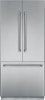
- Thermador T36BT820NS | Installation Manual - Page 1
T36BT810NS T36BT820NS 9000650369 - Thermador T36BT820NS | Installation Manual - Page 2
2 - Thermador T36BT820NS | Installation Manual - Page 3
INSTALLATION INSTRUCTIONS 4 INSTRUCTIONS D'INSTALLATION 24 INSTRUCCIONES DE INSTALACIÓN 44 3 - Thermador T36BT820NS | Installation Manual - Page 4
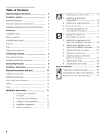
power 8 Grounding instruction 8 Additional grounding procedure 8 Connecting the water 8 Installation dimensions 9 Required the strips 22 8. Adjusting the door spring 22 Special installation 23 Preparing to connect the water 23 Connecting the water to the appliance .. 23 Adjusting - Thermador T36BT820NS | Installation Manual - Page 5
, carpentry and plumbing skills. Proper installation is the responsibility of the installer. Product failure due to improper installation is not covered under the Appliance Warranty. See the Owner's Manual for warranty information. IMPORTANT Save these instructions for local inspector's use. Observe - Thermador T36BT820NS | Installation Manual - Page 6
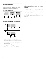
the proper size. Individual appliances with partition When dimensioning the partition for model 4, note the thickness of the furniture fronts to prevent damage if the doors are opened at the same time. Use the Heater Kit for Side-by-Side installation if the gap between the appliances is less - Thermador T36BT820NS | Installation Manual - Page 7
area is at least 4" (100 mm) deep. It is important to observe the specified dimensions of the installation enclosure for a trouble-free installation of the appliance. In particular ensure that the installation enclosure is square. Squareness can be checked by suitable means, e.g. level, diagonal - Thermador T36BT820NS | Installation Manual - Page 8
BottomFreezer 36" Maximal load at one time 6.0 Ampere For the installation position of the receptacle see "Installation dimensions". Grounding instruction This appliance shock. Have the appliance checked by a qualified electrician or service technician if you are in doubt as to whether the - Thermador T36BT820NS | Installation Manual - Page 9
Installation dimensions IMPORTANT ! It is strongly recommended the top panel of the . Legend: A Area for installation of the water connection It is recommended the water-box be placed adjacent to the installation enclosure, so that it can be accessed for service without uninstalling the appliance. If - Thermador T36BT820NS | Installation Manual - Page 10
Operating instructions Installation kit Optional accessories Heater Kit for Side-by-Side installation XHEATKIT10 If the gap between the appliances is less than 6" (160 mm). Other required accessories Ice maker installation kit 1/4" OD copper line For connecting appliances which require water - Thermador T36BT820NS | Installation Manual - Page 11
, CAUTION: Use the following check list for a safe and trouble free installation. 1. Check the floor. See section on "Installation/Floor". 2. Check the dimensions of the installation enclosure, see "Installation dimensions". 3. Check that the installation enclosure is square. 4. Check location - Thermador T36BT820NS | Installation Manual - Page 12
storage compartments inside the appliance until the installation is complete, otherwise the parts may be damaged. Care should be taken when closing the door. The folding rail attached to the door of the refrigerator compartment has to be folded if the door are closed. Risk of damage! When raising - Thermador T36BT820NS | Installation Manual - Page 13
symbol indicates that additional steps need to be taken before proceeding to the next chapter. Special installation steps are described after section B. Connecting the water, see "Preparing to connect the water" and "Connecting the water to the appliance". Door limitation pin, see "Adjusting the - Thermador T36BT820NS | Installation Manual - Page 14
wood board. The length of the plank should correspond to the width of the installation niche! 1. Specify the attachment points of the anti-tip-brackets according to the section on "Installation dimensions". 2. Attach the anti-tip-brackets completely. Be sure screws hold tight. Important notes for - Thermador T36BT820NS | Installation Manual - Page 15
The beam must cover the appliance by at least 2" (50.8 mm). 4. Depending to the subsurface: Locate wall studs in the rear of the installation enclosure and accordingly transfer their location to the wooden beam or fasten suitable dowel into the rear wall. 5. Predrill the wooden beam. 6. Attach the - Thermador T36BT820NS | Installation Manual - Page 16
the screws. These is a special installation step. Instructions are provided after section B. Connecting the water, see "Preparing to connect the water". It is also possible to attach the frame parts directly to the installation enclosure. Note: The frame parts have different hole shapes. Use the - Thermador T36BT820NS | Installation Manual - Page 17
When the floor or the appliance is not leveled in comparison to the installation enclosure adjust height adjustable wheels before you move the appliance into the installation enclosure. 1. Put the mains plug into the socket. 2. Push the water line into the guard tube (a) at the rear of the appliance - Thermador T36BT820NS | Installation Manual - Page 18
screws. Then lift the door off the threaded bolts. 9. Place fixing brackets only loosely into the plates. Ensure that you do not lose them. 10. Remove base panel from the appliance. 12. Remove edge protection (if attached). 11. Carefully push the appliance into the installation enclosure. Push in - Thermador T36BT820NS | Installation Manual - Page 19
Do not twist or jam the appliance inside the installation enclosure! When adjusting the heightadjustable feet, proceed gradually: Always 32 mm) above the floor. It is very important to comply with this dimension for the subsequent alignment of the furniture fronts. The height adjustment gauge (b) - Thermador T36BT820NS | Installation Manual - Page 20
: It is essential to attach the appliance to the top of the installation enclosure. 1. Screw the attachment plate lugs (top) to the overhead Attaching the appliance to the side of the installation enclosure 1. Open the freezer compartment drawer. 2. Screw the fastening brackets to the sidewall of - Thermador T36BT820NS | Installation Manual - Page 21
4. Attaching the toe kick panel Note: Risk of damage to the appliance. Do not cover ventilation slots in the base panel. Nominal dimensions to be observed: Wooden panel 1. If required, shorten wooden panel to the required length. 2. Screw wooden panel to the base panel from behind. There are - Thermador T36BT820NS | Installation Manual - Page 22
panels. If the depth alignment is correct, tighten the screws on the fixing brackets. 4. Screw nuts onto the threaded bolts on top of the door. Do not tighten yet. 5. Check lateral alignment of the stainless steel front panel. If the lateral alignment is correct, tighten the nuts. 8. Adjusting the - Thermador T36BT820NS | Installation Manual - Page 23
Turn off the main water tap to prevent damage caused by leaking water. 1. Attach the water line to the shut-off valve according to the instructions supplied by the manufacturer of the ice maker installation kit. 2. Install the water line. Always observe the indicated dimensions to prevent damage to - Thermador T36BT820NS | Installation Manual - Page 24
Instructions de raccordement à la terre 28 Procédure additionnelle de mise à la terre .......... 28 Raccordement de l'eau 28 Dimensions d'installation Retirer le cadre 36 5. Pousser l'appareil dans la cavité d'installation 37 1. Alignement de l'appareil dans la cavité d'installation 39 2. - Thermador T36BT820NS | Installation Manual - Page 25
qu'il ait été installé et sécurisé conformément aux instructions d'installation. Vu le poids et à un technicien qualifié du service après-vente. REMARQUE L'installation de cet appareil oblige à . En l'absence de réglementation locale : - Aux USA : en conformité avec le National Electric Code, ANSI - Thermador T36BT820NS | Installation Manual - Page 26
situés au-dessus avant de placer l'appareil dans la cavité. Pour dimensionner le panneau latéral, basez-vous sur les dimensions du panneau opposé formant la cavité. Pendant l'installation, veillez à ce que la cavité reste à angles droits et qu'elle ait la taille exacte. Appareils individuels avec - Thermador T36BT820NS | Installation Manual - Page 27
°C). L'appareil est très lourd. BottomFreezer 36": Le poids à vide env. 430 Ibs/195 kg Local d'installation Il faudra installer l'appareil dans une pièce sèche soit esthétique, il est important que la cavité d'installation ait bien les dimensions spécifiées. Assurez-vous en particulier que la cavité - Thermador T36BT820NS | Installation Manual - Page 28
par un coupe-circuit ou un fusible supportant 15 A. Appareil BottomFreezer 36" Ampérage instantané maximal 6.0 ampères En ce qui concerne la position d'installation de la prise femelle, veuillez vous reporter à la section « Dimensions d'installation ». Instructions de raccordement à la terre Cet - Thermador T36BT820NS | Installation Manual - Page 29
Dimensions d'installation IMPORTANT ! Nous suggérons instamment de former la limite supérieure pas possible, placez la boîte à eau dans la zone foncée. B Représente la zone où installer le raccordement de l'électricité. C Profondeur d'ouverture de la cavité, ceci dépendant de la configuration de la - Thermador T36BT820NS | Installation Manual - Page 30
Instructions d'installation Instructions d'utilisation Kit d'installation dimensions Madrier (section minimum 3" x 4") à titre de protection alternative contre le renversement, d'une longueur correspondant à la cavité d'installation Embout Torx T20 / T30 + support magnétique Tournevis Torx T20 - Thermador T36BT820NS | Installation Manual - Page 31
sûre et sans contretemps, utilisez la check-list suivante : 1. Vérifiez le sol. Suivez les instructions dans la section «Lieu d'installation». 2. Vérifiez la dimension de la cavité. Suivez les instructions dans la section « Dimensions d'installation». 3. Vérifiez que la cavité présente des - Thermador T36BT820NS | Installation Manual - Page 32
la porte. Remarque: N'enlevez les cales de transport, servant à protéger les tiroirs et casiers de rangement dans l'appareil, qu'après avoir achevé l'installation, car ces pièces risquent sinon d'être endommagées. Attention lors de la fermeture de la porte. Lors de la fermeture des portes, il - Thermador T36BT820NS | Installation Manual - Page 33
spéciale Ce symbole indique des étapes de travail supplémentaires à effectuer avant de passer au chapitre suivant. Les étapes d'installation spéciales sont décrites au-delà de la section B. Raccordement de l'eau, voir « Préparation du raccordement de l'eau » et « Raccordement de l'eau à l'appareil - Thermador T36BT820NS | Installation Manual - Page 34
! 1. Définissez les points de fixation des cornières anti- renversement. Déterminez les dimensions détaillées conformément à la section « Dimensions d'installation ». 2. Fixez complètement les cornières antirenversement. Assurez-vous que les vis tiennent fermement. Remarques importantes - Thermador T36BT820NS | Installation Manual - Page 35
cavité d'installation est plus profonde que l'appareil, sélectionnez un madrier qui présente une plus forte section ou fixez 2 madriers l'un contre l'autre. Le madrier doit recouvrir l'appareil sur au moins 2" (50,8 mm). 4. Suivant la nature de la surface support : Recherchez des supports dans la - Thermador T36BT820NS | Installation Manual - Page 36
après avoir desserré les vis. Il s'agit d'étapes d'installation spéciales. Des instructions sont fournies au-delà de la section B. Raccordement de installation. Remarque : Les pièces du cadre présentent des trous de formes différentes. Pour effectuer le montage, utilisez les trous biseautés. 36 - Thermador T36BT820NS | Installation Manual - Page 37
au centre derrière l'appareil, à env. 15" (380 mm) du panneau arrière de la cavité. 4. Poussez prudemment l'appareil à moitié dans la cavité d'installation. 5. Enlevez la cale de transport située contre la face inférieure du tiroir du compartiment congélateur. 6. Desserrez les écrous situés en haut - Thermador T36BT820NS | Installation Manual - Page 38
. Enfoncez l'appareil jusqu'à ce que le cadre (s'il n'a pas été démonté auparavant) se trouve contre les parois de la cavité d'installation. Tirez la corde pour empêcher le cordon de se coincer. 8. Pour détacher les brides de fixation des vis, éloignez le bas de la faç - Thermador T36BT820NS | Installation Manual - Page 39
1. Alignement de l'appareil dans la cavité d'installation Remarque: Pour assurer que l'appareil fonctionne correctement, il faut le niveler impeccablement. Ne /2" (32 mm) au-dessus du Il est très important de respecter cette dimension pour pouvoir ensuite aligner les façades des meubles. 39 - Thermador T36BT820NS | Installation Manual - Page 40
importance cruciale de fixer l'appareil contre le plafond de la cavité d'installation. 1. Vissez les pattes de fixation (en haut) contre le meuble/les importante au dessus de l'appareil, montez impérativement un madrier aux dimensions adaptées et sans jeu au dessus de l'appareil. 4. Raccourcissez - Thermador T36BT820NS | Installation Manual - Page 41
(ne le vissez pas dessus). 2. Retirez la pellicule protectrice des bandes adhésives. 2. Retirez le panneau de base. 3. Ajustez les brides (a) aux dimensions A puis vissez à fond. 3. Présentez le panneau de socle devant le panneau de base et poussez fermement pour le fixer. 4. Fixez le bandeau - Thermador T36BT820NS | Installation Manual - Page 42
6. Montage de la façade en acier inoxydable contre le tiroir du compartiment congélateur 1. Accrochez la façade en acier inoxydable aux goujons à double filetage. 2. Abaissez la façade de la porte et enfoncez les brides de fixation sur leurs vis. 7. Fixation des couvercles 1. Fixez les baguettes - Thermador T36BT820NS | Installation Manual - Page 43
la conduite de raccordement contre la vanne de fermeture en respectant les instructions fournies par le fabricant du kit destiné à l'installation du distributeur de glaçons. 2. Installez la conduite de raccordement. Respectez toujours les dimensions spécifiées pour l'espace libre, ceci pour empêcher - Thermador T36BT820NS | Installation Manual - Page 44
cuadro 56 5. Colocando el electrodoméstico en la cavidad de instalación 57 1. Alineación del electrodoméstico ...... 59 2. Sujetando el electrodoméstico a la parte superior de la cavidad ..... 60 3. Sujeción del electrodoméstico en los laterales de la cavidad 60 4. Sujeción del panel de protecci - Thermador T36BT820NS | Installation Manual - Page 45
INSTRUCCIONES IMPORTANTES DE SEGURIDAD , ADVERTENCIA General La parte superior de este electrodoméstico es más pesada debido a una instalación inadecuada no esta cubiertos por la garantía. Consulte el manual del usuario por la información concerniente a la garantía. IMPORTANT Las reparaciones - Thermador T36BT820NS | Installation Manual - Page 46
Opciones de instalación Existen diversas opciones de instalación. Están limitadas exclusivamente por el diseño de la cocina. Ver también «Breve referencia para diseño de cocina (Kitchen Design Quick Reference)». Unidad individual Electrodomésticos individuales en el final de las unidades de cocina - Thermador T36BT820NS | Installation Manual - Page 47
instale el electrodoméstico: a la intemperie, en un sitio con presencia de agua, en ambientes a temperaturas inferiores a los 32 °F (0 °C). El electrodoméstico es muy pesado. Por los pesos del equipo vacío, consulte la tabla siguiente: Congelador independiente de 36 que forman parte del volumen - Thermador T36BT820NS | Installation Manual - Page 48
con la licencia debida. El tomacorriente debe estar protegido mediante un fusible o térmico de 15 A. Electrodoméstico Congelador independiente de 36" (2 puertas) Carga simultánea máxima 6.0 Amper Por la ubicación de los tomacorrientes, consulte las «Medidas de emplazamiento». Instrucciones de - Thermador T36BT820NS | Installation Manual - Page 49
una profundidad mínima de 4" (100 mm). Leyenda: A Zona para la instalación de la conexión de agua. Recomendamos que el depósito de agua se instale al lado abertura de instalación, por razones de servicio, de modo que pueda accederse al mismo sin desinstalar el electrodoméstico. Si no fuera posible - Thermador T36BT820NS | Installation Manual - Page 50
Accesorios y herramientas necesarias Accesorios que forman parte volumen de entrega - Instrucciones para el montaje - Instrucciones de funcionamiento - Juego de instalación Herramientas Accesorios opcionales Combinación y calentamiento XHEATKIT10 Si el espacio entre los electrodomé - Thermador T36BT820NS | Installation Manual - Page 51
Nota: Controle si el electrodoméstico presenta daños de transporte. No instale el electrodoméstico si presenta daños visibles. En caso de dudas, de las esquinas"). Nota: No quite el seguro de transporte (a) de la parte inferior del cajón que se encuentra en el gabinete de congelación. 4. Soltar - Thermador T36BT820NS | Installation Manual - Page 52
- doméstico sujetandolo de las paredes laterales! Nota: Aplicar la carretilla de transporte siempre en el centro de la parte posterior del aparato. ¡No aplicarla nunca en la parte frontal o en uno de los laterales! ¡El aparato puede sufrir daños o desperfectos! 3. Transporte del electrodoméstico - Thermador T36BT820NS | Installation Manual - Page 53
de montaje y los accesorios. A fin de simplificar la instalación, el embalaje se identifica mediante etiquetas A y B, correspondientemente a las seccionas del manual. 5. Instalación especial Esto significa que deben cumplimentarse pasos adicionales antes de pasar al capítulo siguiente. Los pasos de - Thermador T36BT820NS | Installation Manual - Page 54
1. Colocación de los angulos antivuelco , ADVERTENCIA: ¡Existe peligro de lesiones y daños! Asegure que no existan cables eléctricos o tuberías en la zonas donde deben penetrar los tornillos. , ATENCIÓN: ¡Peligro de lesiones! Utilice siempre gafas y otros dispositivos de protección cuando instala - Thermador T36BT820NS | Installation Manual - Page 55
2. Montaje de un dispositivo antivuelco adicional Importante: Si no se pueden montar los ángulos antivuelco con la firmeza requerida, puede montarse un dispositivo antivuelco alternativo. Sin embargo, debe asegurarse, de que no exista juego entre el electrodoméstico y el dispositivo antivuelco. Si - Thermador T36BT820NS | Installation Manual - Page 56
dan después de la sección B. Por la conexión del agua, ver «Preparación para conectar el agua». También es posible sujetar las partes del cuadro directamente en el encerramiento de instalación. Nota: Los orificios del cuadro poseen diferentes medidas. Utilizar las perforaciones del chanfle para - Thermador T36BT820NS | Installation Manual - Page 57
la cavidad. 1. Conecte el enchufe en el tomacorriente. 2. Introducir la alimentación de agua en el tubo de protección (a) que se encuentra en la parte posterior del electrodoméstico. , ADVERTENCIA: Obrar con cuidado para que no se lastimen las personas que ayudan en la instalación ni evitar que se - Thermador T36BT820NS | Installation Manual - Page 58
8. Alejar la parte inferior del panel frontal de acero inoxidable de la puerta a fin de quitar las placas de sujeción de los tornillos. Levantar luego la puerta sobre - Thermador T36BT820NS | Installation Manual - Page 59
en sentido vertical, haciendo uso de las patas posteriores. ¡Utilizar un nivel! Las ruedas de altura ajustable tanto del frente como de la parte posterior, pueden ajustarse desde el frente. Frente: Fondo: Llave de boca de 1/2" (13 mm) Destornillador en cruz 5/16" (8 mm) con vástago flexible. 59 - Thermador T36BT820NS | Installation Manual - Page 60
longitud requerida para cerrar el espacio libre. 5. Presionar el listón de sujeción (a) contra el listón de cobertura (superior). 6. Sujete el listón de cobertura (b) en la placa de montaje (arriba). 3. Si existe suficiente espacio en la parte superior del electrodoméstico, sujetar la las piezas de - Thermador T36BT820NS | Installation Manual - Page 61
de madera 1. Si hiciera falta, cortar el panel de madera a la longitud necesaria. 2. Atornillar el panel de madera en el panel base desde la parte posterior. También hay perforaciones para los tornillos en el panel base. 5. Alineación del panel de protección 1. Aplique el panel base (sin atornillar - Thermador T36BT820NS | Installation Manual - Page 62
. Si la alineación es correcta, ajustar los tornillos de los elementos de sujeción. 4. Enroscar las tuercas en los pernos insertados en la parte superior de la puerta. No ajustar todavía. 5. Controlar la alineación lateral del panel de acero inoxidable. Si la alineación es correcta, ajustar - Thermador T36BT820NS | Installation Manual - Page 63
Monte la tubería de conexión a la válvula de cierre, según las instrucciones suministradas por el fabricante de la instalación generadora de hielo. 2. Instale la tubería de conexión. Observe siempre las medidas de separación indicadas, a fin de evitar daños en la tubería de conexión, cuando coloca - Thermador T36BT820NS | Installation Manual - Page 64
9000650369 (9107) en-us, fr-ca, es-mex
-
 1
1 -
 2
2 -
 3
3 -
 4
4 -
 5
5 -
 6
6 -
 7
7 -
8
-
9
-
10
-
11
-
12
-
13
-
14
-
15
-
16
-
17
-
18
-
19
-
20
-
21
-
22
-
23
-
24
-
25
-
26
-
27
-
28
-
29
-
30
-
31
-
32
-
33
-
34
-
35
-
36
-
37
-
38
-
39
-
40
-
41
-
42
-
43
-
44
-
45
-
46
-
47
-
48
-
49
-
50
-
51
-
52
-
53
-
54
-
55
-
56
-
57
-
58
-
59
-
60
-
61
-
62
-
63
-
64
 |
 |
9000650369
T36BT810NS
T36BT820NS