Toshiba HD-A30 Owners Manual - Page 10
Index to parts and controls - bitstream
 |
UPC - 022265000908
View all Toshiba HD-A30 manuals
Add to My Manuals
Save this manual to your list of manuals |
Page 10 highlights
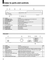
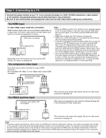
Index to parts and controls Front panel 12 3 4 5 6 No. Control 1 ON/STANDBY button 2 ON/STANDBY indicator 3 Front panel display 4 Remote sensor 5 Disc tray 6 Extension port 7 / (SKIP) buttons 8 (PAUSE) button 9 (STOP) button 10 (PLAY) button 11 OPEN/CLOSE button Rear panel 1 7 8 9 10 11 Function Turns the power on or restores the unit to the standby mode. Blue: power on / Red: standby mode See the next page. Receives infrared signals from the remote control. Loads a disc into the disc drive. For future functions. Locates a chapter or track. : forward direction / : reverse direction Stops playback momentarily. Stops playback. Starts playback. Opens and closes the disc tray. Page 18 18 11 13 24 28 25 25 25 24 24 2 34 56 7 8 No. Control Function Page 1 AC IN socket Connect the supplied power cord. 17 2 Ventilation fan Do not cover the ventilation holes. - 3 LAN port Use this to connect to a network with an always-on broadband connection. 17 4 DIGITAL AUDIO OUTPUT BITSTREAM/ PCM OPTICAL jack Outputs digital audio signals. Connect to a digital audio input on an amplifier equipped with digital audio decoder. When connecting the optional digital cable, fit the connector into the jack firmly. 16 5 VIDEO OUTPUT jack Outputs video signals to a connected TV or amplifier. 15 6 COMPONENT VIDEO OUTPUT jacks Outputs video signals to a connected TV or monitor. Connect to a TV or monitor equipped with component video jacks. 15 7 HDMI OUTPUT jack Outputs video/audio signals to a connected TV, monitor or AV amplifier. Connect to a TV, monitor or AV amplifier equipped with HDMI input. 15 8 ANALOG AUDIO OUTPUT jacks Outputs audio signals to a connected TV or AV amplifier. 16 10
-
 1
1 -
2
-
3
-
4
-
 5
5 -
 6
6 -
 7
7 -
 8
8 -
 9
9 -
 10
10 -
 11
11 -
 12
12 -
 13
13 -
 14
14 -
 15
15 -
16
-
17
-
18
-
19
-
20
-
21
-
22
-
23
-
24
-
25
-
26
-
27
-
28
-
29
-
30
-
31
-
32
-
33
-
34
-
35
-
36
-
37
-
38
-
39
-
40
-
41
-
42
-
43
-
44
-
45
-
46
-
47
-
48
 |
 |
