Toshiba Tecra A3-S611 Maintenance Manual - Page 134
Installing the Display Assembly, Replacement Procedures,
 |
View all Toshiba Tecra A3-S611 manuals
Add to My Manuals
Save this manual to your list of manuals |
Page 134 highlights
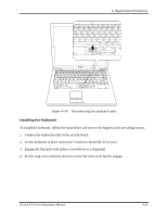
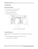
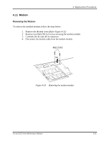
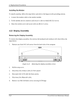
M2.5X8 4 Replacement Procedures 1 2 M2.5X8 Figure 4-22 Removing the wireless and LCD cables 7. Lift the display assembly from the computer's chassis. Installing the Display Assembly To install the display assembly, follow the steps below and refer to the figures in the preceding section. 1. Seat the display assembly taking care not to crush to the LCD cable or wireless cable. 2. Secure two M2.5x8 black screws to LCD hinge. 3. Connect the LCD cable to the top chassis. 4. Connect the wireless cable to the wireless module. 5. Connect the Bluetooth cable to the Bluetooth module. 6. Reinstall the strip cover and the keyboard. 7. Secure two black M2.5x8 screws on the back of the computer. Tecra A3/S2 Series Maintenance Manual 4-27
-
 1
1 -
2
-
3
-
4
-
5
-
6
-
7
-
8
-
9
-
10
-
11
-
12
-
13
-
14
-
15
-
16
-
17
-
18
-
19
-
20
-
21
-
22
-
23
-
24
-
25
-
26
-
27
-
28
-
29
-
30
-
31
-
32
-
33
-
34
-
35
-
36
-
37
-
38
-
39
-
40
-
41
-
42
-
43
-
44
-
45
-
46
-
47
-
48
-
49
-
50
-
51
-
52
-
53
-
54
-
55
-
56
-
57
-
58
-
59
-
60
-
61
-
62
-
63
-
64
-
65
-
66
-
67
-
68
-
69
-
70
-
71
-
72
-
73
-
74
-
75
-
76
-
77
-
78
-
79
-
80
-
81
-
82
-
83
-
84
-
85
-
86
-
87
-
88
-
89
-
90
-
91
-
92
-
93
-
94
-
95
-
96
-
97
-
98
-
99
-
100
-
101
-
102
-
103
-
104
-
105
-
106
-
107
-
108
-
109
-
110
-
111
-
112
-
113
-
114
-
115
-
116
-
117
-
118
-
119
-
120
-
121
-
122
-
123
-
124
-
125
-
126
-
127
-
128
-
 129
129 -
 130
130 -
 131
131 -
 132
132 -
 133
133 -
 134
134 -
 135
135 -
 136
136 -
 137
137 -
 138
138 -
 139
139 -
140
-
141
-
142
-
143
-
144
-
145
-
146
-
147
-
148
-
149
-
150
-
151
-
152
-
153
-
154
-
155
-
156
-
157
-
158
-
159
-
160
-
161
-
162
-
163
-
164
-
165
-
166
-
167
-
168
-
169
-
170
-
171
-
172
-
173
-
174
-
175
-
176
-
177
-
178
-
179
-
180
-
181
-
182
-
183
-
184
-
185
-
186
-
187
-
188
-
189
-
190
-
191
-
192
-
193
-
194
-
195
-
196
-
197
-
198
-
199
-
200
-
201
-
202
 |
 |
4
Replacement Procedures
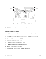
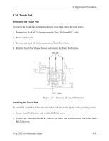
1
2
M2.5X8
M2.5X8
Figure 4-22
Removing the wireless and LCD cables
7.
Lift the display assembly from the computer’s chassis.
Installing the Display Assembly
To install the display assembly, follow the steps below and refer to the figures in the preceding
section.
1.
Seat the display assembly taking care not to crush to the LCD cable or wireless cable.
2.
Secure two M2.5x8 black screws to LCD hinge.
3.
Connect the LCD cable to the top chassis.
4.
Connect the wireless cable to the wireless module.
5.
Connect the Bluetooth cable to the Bluetooth module.
6.
Reinstall the strip cover and the keyboard.
7.
Secure two black M2.5x8 screws on the back of the computer.
Tecra A3/S2
Series Maintenance Manual
4-27