Tripp Lite SU3000XL Owner's Manual for SmartOnline UPS 932470 - Page 4
Installation - tripp
 |
View all Tripp Lite SU3000XL manuals
Add to My Manuals
Save this manual to your list of manuals |
Page 4 highlights
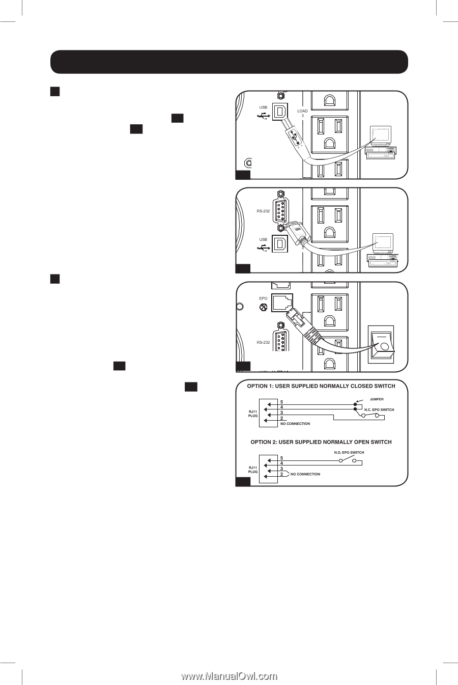
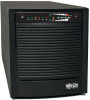
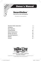
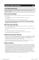
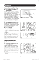
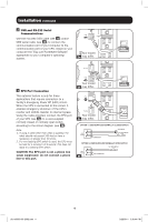
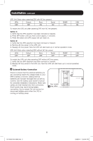
Installation continued 2 USB and RS-232 Serial Communications Use the included USB cable (see 2a ) and/or DB9 serial cable (see 2b ) to connect the communication port of your computer to the communication port of your UPS. Install on your computer the Tripp Lite PowerAlert Software appropriate to your computer's operating system. Your model 2a may differ. 3 EPO Port Connection Your model 2b may differ. This optional feature is only for those applications that require connection to a facility's Emergency Power Off (EPO) circuit. When the UPS is connected to this circuit, it enables emergency shutdown of the UPS's inverter and inhibits transfer to internal bypass. Using the cable provided, connect the EPO port of your UPS (see 3a ) to a user-supplied normally closed or normally open switch according to the circuit diagram (see 3b ). Your model 3a may differ. Note: 4-5 1. If using a cable other than what is supplied, the cable should not exceed 350 feet or have a resistance of greater than 10 ohms. 2. If a non-latching EPO switch is used, the EPO must be held for a minimum of 1 second. This does not apply to a latching EPO switch. CAUTION: The EPO port is not a phone line surge suppressor; do not connect a phone 3b line to this port. 4 201102091 93-3092.indb 4 3/29/2011 5:36:44 PM
-
 1
1 -
 2
2 -
 3
3 -
 4
4 -
 5
5 -
 6
6 -
 7
7 -
 8
8 -
 9
9 -
 10
10 -
11
-
12
-
13
-
14
-
15
-
16
-
17
-
18
-
19
-
20
-
21
-
22
-
23
-
24
-
25
-
26
-
27
-
28
-
29
-
30
-
31
-
32
-
33
-
34
-
35
-
36
-
37
-
38
-
39
-
40
 |
 |