Vaddio RoboSHOT 30 HDMI User Guide - Page 8
CAMERA SETTINGS, HD VIDEO SELECT, NETWORK CONTROL Port, RS-232 Port Color Coded Blue, HDMI Connector
 |
View all Vaddio RoboSHOT 30 HDMI manuals
Add to My Manuals
Save this manual to your list of manuals |
Page 8 highlights
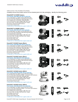
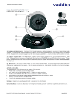
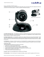
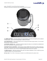
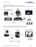
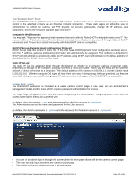
RoboSHOT HDMI Series Cameras Image: RoboSHOT 12 and 30 Rear Panel Connections Rear panel connections are identical for both models (RoboSHOT 12 shown). ① ④ ② ⑤ ⑥ ③ 1) CAMERA SETTINGS: DIP switch settings for IR remote frequency, baud rate and image flip can be configured on these switches. See the Switch Settings page for additional information. 2) HD VIDEO SELECT: A rotary switch allows the user to choose the HD video output resolution. See the Switch Settings page for additional information. 3) NETWORK CONTROL Port: The Ethernet 10/100 port allows the camera to be controlled from embedded web server with a web browser or through Telnet session. 4) RS-232 Port (Color Coded Blue): The RS-232 port accepts modified VISCA protocol for camera control over a Cat-5e cable. This port also acts as an IR Forwarding port with the Quick-Connect SR or Quick-Connect DVI/HDMI interfaces, which allows the user to transmit 3rd party IR signals through camera to the head-end. 5) HDMI Connector: HDMI video output jack (the output Color Space is defaulted to YCbCr for HDMI, but can be switched to sRGB for DVI-D only video devices). 6) Power Jack: The 12 VDC, 3.0 Amp power connector is on an EIAJ-04 jack with a positive center. RoboSHOT HDMI Series Camera Manual - Document Number 342-1001 Rev A Page 8 of 40
-
 1
1 -
2
-
 3
3 -
 4
4 -
 5
5 -
 6
6 -
 7
7 -
 8
8 -
 9
9 -
 10
10 -
 11
11 -
 12
12 -
 13
13 -
14
-
15
-
16
-
17
-
18
-
19
-
20
-
21
-
22
-
23
-
24
-
25
-
26
-
27
-
28
-
29
-
30
-
31
-
32
-
33
-
34
-
35
-
36
-
37
-
38
-
39
-
40
 |
 |
