ViewSonic LS800HD LS800HD User Guide English - Page 14
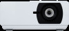
Projector exterior view
 |
View all ViewSonic LS800HD manuals
Add to My Manuals
Save this manual to your list of manuals |
Page 14 highlights
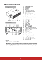
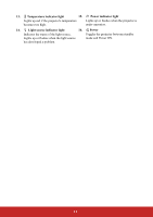
Projector exterior view Front/upper side 12 3 4 5 6 7 8 9 Rear/lower side 10 11 12 13 14 15 16 17 18 19 20 21 22 23 24 25 26 27 28 23 Warning • THIS APPARATUS MUST BE EARTHED. 1. Front IR remote sensor 2. Projection lens 3. Focus ring 4. Zoom ring 5. LENS SHIFT UP/DOWN 6. LENS SHIFT RIGHT/LEFT 7. Vent (air inlet) 8. External control panel (See "Projector" on page 10 for details.) 9. Power button and top IR remote sensor 10. AC power cord inlet 11. HDMI 1 port 12. HDMI 2 port 13. LAN port 14. HDMI 3 port 15. HDBaseT port 16. Monitor out socket 17. RS232 control port 18. Computer In/Component video (YPbPr/YCbCr) signal input socket 19. Video input socket 20. 3D Sync port 21. Mini USB port 22. USB port (5V/1.5A out) 23. Adjuster foot 24. Audio signal output socket 25. Mic input socket 26. Audio signal input socket 27. Audio signal input L/R socket 28. Kensington lock • When installing the unit, incorporate a readily accessible disconnect device in the fixed wiring, or connect the power plug to an easily accessible socket-outlet near the unit. If a fault should occur during operation of the unit, operate the disconnect device to switch the power supply off, or disconnect the power plug. 9
-
 1
1 -
2
-
3
-
4
-
5
-
6
-
7
-
8
-
 9
9 -
 10
10 -
 11
11 -
 12
12 -
 13
13 -
 14
14 -
 15
15 -
 16
16 -
 17
17 -
 18
18 -
 19
19 -
20
-
21
-
22
-
23
-
24
-
25
-
26
-
27
-
28
-
29
-
30
-
31
-
32
-
33
-
34
-
35
-
36
-
37
-
38
-
39
-
40
-
41
-
42
-
43
-
44
-
45
-
46
-
47
-
48
-
49
-
50
-
51
-
52
-
53
-
54
-
55
-
56
-
57
-
58
-
59
-
60
-
61
-
62
-
63
-
64
-
65
-
66
-
67
-
68
-
69
-
70
-
71
-
72
-
73
-
74
-
75
-
76
-
77
-
78
-
79
-
80
-
81
-
82
-
83
-
84
-
85
-
86
-
87
-
88
-
89
-
90
-
91
-
92
-
93
-
94
-
95
-
96
-
97
-
98
-
99
-
100
-
101
 |
 |
