ViewSonic VT2755LED User Manual - Page 15
Rear View of the Product
 |
View all ViewSonic VT2755LED manuals
Add to My Manuals
Save this manual to your list of manuals |
Page 15 highlights
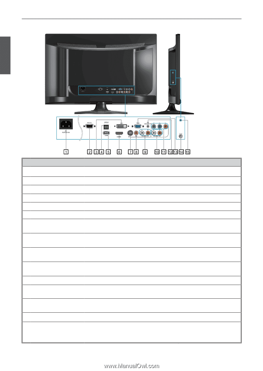
Getting Started Rear View of the Product ENGLISH Item Description 1 Power (AC input) Plug-in the supplied AC Power cord and connect to the AC input power source. 2 RS232 signal input This port is for the service technician's use. 3 DVI signal input Connect this port to the DVI output of PC device. 4 SPDIF Optical output Connect this port to the SPDIF input of A/V device. 5 USB Connect to your USB devices, such as USB flash drive. 6 HDMI Input Terminal Connect this port to the HDMI output of PC device. 7 S-Video input Connect the S-Video cable from the compatible device to this connector on the rear panel of the LCD TV. 8 Composite Video input Connect this jack to the composite video output connectors on your A/V equipment. 9 AV/ S-Video Audio input (left/ right) 10 YPbPr signal Audio input (left/ right) 11 YPbPr signal input 12 PC Audio input 13 VGA signal input Connect the Audio in cable for AV/ S-Video from this jack to the corresponding connectors on your A/V device. Connect the Audio in cable for YPbPr from this jack to the corresponding connectors on your A/V device. Connect this port to the YPbPr output of A/V device. Connect the RGB Audio Out on your computer to the RGB Audio on the rear of the LCD TV. Connect a 15-pin D-sub RGB cable to the RGB output of your computer and the other end to the RGB input on the rear of the LCD TV. 14 TV Input Jack Connect this jack to your Cable or VHF/UHF antenna. 15 Headphone Jack Connect to your headphones. By connecting the headphones, you can listen to the sound from the TV on headphones. *If you connect the headphones, the TV speakers will be muted. ViewSonic 6 VT2755LED
-
 1
1 -
2
-
3
-
4
-
5
-
6
-
7
-
8
-
9
-
 10
10 -
 11
11 -
 12
12 -
 13
13 -
 14
14 -
 15
15 -
 16
16 -
 17
17 -
 18
18 -
 19
19 -
 20
20 -
21
-
22
-
23
-
24
-
25
-
26
-
27
-
28
-
29
-
30
-
31
-
32
-
33
-
34
-
35
-
36
-
37
-
38
-
39
-
40
-
41
-
42
-
43
-
44
-
45
-
46
-
47
-
48
-
49
-
50
-
51
-
52
-
53
-
54
-
55
-
56
-
57
-
58
-
59
 |
 |