ViewSonic VX2262WM Service Manual - Page 23
LD7552DPS IC901, Function
 |
UPC - 766907303919
View all ViewSonic VX2262WM manuals
Add to My Manuals
Save this manual to your list of manuals |
Page 23 highlights
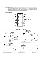
LD7552DPS (IC901): PWM control, high-voltage startup current. The circuit unit has functions such as over-current protection, over-voltage protection, output short-circuit protection and etc. The function of each pin and the inside circuit diagram are as follows: Pin Name Function 1 GND Ground Voltage feedback pin (same as the COMP pin in UC384X), By 2 COMP connecting a photo-coupler to close the control loop and achieve the regulation 3 VCC Supply voltage pin 4 RT This pin is to program the switching frequency. By connecting a resistor to ground to set the switching frequency. 6 NC Unconnected pin 7 VCC Supply voltage pin 8 OUT Gate drive output to drive the external MOSFET ViewSonic Corporation - 23 - Confidential - Do Not Cop VX2262wm/wmp
-
 1
1 -
2
-
3
-
4
-
5
-
6
-
7
-
8
-
9
-
10
-
11
-
12
-
13
-
14
-
15
-
16
-
17
-
 18
18 -
 19
19 -
 20
20 -
 21
21 -
 22
22 -
 23
23 -
 24
24 -
 25
25 -
 26
26 -
 27
27 -
 28
28 -
29
-
30
-
31
-
32
-
33
-
34
-
35
-
36
-
37
-
38
-
39
-
40
-
41
-
42
-
43
-
44
-
45
-
46
-
47
-
48
-
49
-
50
-
51
-
52
-
53
-
54
-
55
-
56
-
57
-
58
-
59
-
60
-
61
-
62
-
63
-
64
-
65
-
66
-
67
-
68
-
69
-
70
-
71
-
72
-
73
-
74
-
75
-
76
-
77
-
78
-
79
-
80
-
81
-
82
-
83
 |
 |
