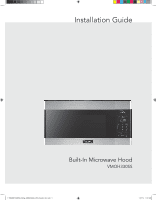
Viking VMOH330 Installation Instructions - Page 3
Wall Construction, Electrical, Grounding, Instructions
 |
View all Viking VMOH330 manuals
Add to My Manuals
Save this manual to your list of manuals |
Page 3 highlights
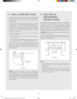
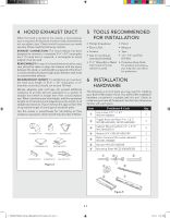
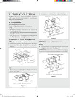
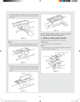
2 WALL CONSTRUCTION This Built-In Microwave Hood should be mounted against and supported by a flat vertical wall. The wall must be flat for proper installation. If the wall is not flat, use spacers to fill in the gaps. Wall construction should be a minimum of 2" x 4" wood studding and 3/8" or more thick drywall or plaster/lath. The mounting surfaces must be capable of supporting a weight of 110 pounds-the oven and contents-AND the weight of all items which would normally be stored in the top cabinet above the unit. The unit should be attached to a minimum of one 2" x 4" wall stud. To find the location of the studs, one of the following methods may be used: • Use a stud finder, a magnetic device which locates the nails in the stud. • Use a hammer to tap lightly across the mounting surface to find a solid sound. This will indicate stud location. The center of the stud can be located by probing the wall with a small nail to find the edges of the stud and then placing a mark halfway between the edges. The center of any adjacent studs will normally be 16" or 24" to either side of this mark. 3 ELECTRICAL GROUNDING INSTRUCTIONS This appliance must be grounded. This oven is equipped with a cord having a grounding wire with a grounding plug. It must be plugged into a wall receptacle that is properly installed and grounded in accordance with the National Electrical Code and local codes and ordinances. In the event of an electrical short circuit, grounding reduces risk of electric shock by providing an escape wire for the electric current. WARNING - Improper use of the grounding plug can result in a risk of electric shock. The Power Supply Cord and plug must be connected to a separate 120 Volt AC, 60 Hz, 15 Amp, or more branch circuit, single grounded receptacle. Ground Receptacle 16" or 24" 2"x 4" Wood Studs Opening for Power Cord Figure 3 3/8" Dry Wall or Plaster/Lath Figure 2 NOTE: In the event that the unit will be unable to be supported by any stud, it will be necessary to use special care in the placement of the toggle bolts and top cabinet screws. See Wall Template for details. The top cabinet should be tested to ensure it is securely attached to the wall. Place extra weight up to 110 pounds inside the top cabinet to test the support. NOTE: 1. If you have any questions about the grounding or electrical instructions, consult a qualified electrician or serviceperson. 2. Neither Viking Range, LLC nor the dealer can accept any liability for damage to the oven or personal injury resulting from failure to observe the correct electrical connection procedures. 1.TINSKB278MRR0_Viking_VMOH330SS_OTR_Install_E,S,F.indd 3 E 3 1/31/19 11:07 AM
-
 1
1 -
 2
2 -
 3
3 -
 4
4 -
 5
5 -
 6
6 -
 7
7 -
 8
8 -
 9
9 -
10
-
11
-
12
-
13
-
14
-
15
-
16
-
17
-
18
-
19
-
20
-
21
-
22
-
23
-
24
-
25
-
26
-
27
-
28
-
29
-
30
-
31
-
32
-
33
-
34
-
35
-
36
 |
 |
