Viking VMOH330 Installation Instructions - Page 4
Hood Exhaust Duct, Tools Recommended, For Installation, Installation, Hardware
 |
View all Viking VMOH330 manuals
Add to My Manuals
Save this manual to your list of manuals |
Page 4 highlights
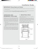
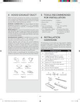
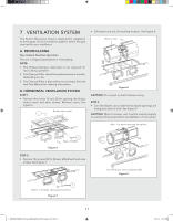
4 HOOD EXHAUST DUCT When the hood is vented to the outside, a hood exhaust duct is required. All ductwork must be metal; absolutely do not use plastic duct. Check that all connections are made securely. Please read the following carefully: EXHAUST CONNECTION: The hood exhaust has been designed to connect to a standard 31/4" x 10" rectangular duct. If round duct is required, a rectangular-to-round adapter must be used. REAR EXHAUST: If a rear or horizontal exhaust is to be used, care should be taken to align the exhaust with the space between the studs, or wall should be prepared at the time it is constructed by leaving enough space between wall studs to accommodate exhaust. MAXIMUM DUCT LENGTH: For satisfactory air movement, the total duct length of 31/4" x 10" rectangular or 6" diameter round duct should not exceed 140 feet. Elbows, adapters, wall, roof caps, etc. present additional resistance to air flow and are equivalent to a section of straight duct which is longer than their actual physical size. When calculating the total length, add the equivalent lengths of all transitions and adapters plus the length of all straight duct sections. Figure 4 shows the approximate feet of equivalent length of some typical ductwork parts. Use the values in parentheses for calculating air flow resistance equivalent, which should total less than 140 feet. 5 TOOLS RECOMMENDED FOR INSTALLATION • Phillips Screwdriver • Electric Drill • Scissors • Saw to cut exhaust opening (if needed) • 11/2" Wood Bit or Metal Hole Cutter (if metal cabinet is used) • Pencil • Measure • Tape • 1/2", 5/8" and 3/32" Drill Bits • Protective Drop Cloth for product and range- you may also use carton for protection 6 INSTALLATION HARDWARE The following is a list of parts you may need for installing your Built-In Microwave Hood. You will find the installation hardware contained in a packet with the unit. Check to make sure you have all these parts. Use this time to become familiar with each piece. Item Part Name & Code Qty 1 Lag screws (1/4" x 1.8") 9KC7117604511 2 2 Toggle Bolts and Nuts 3/16" x 2.7" 9KC3516003200, 9KC3516003300 2 3 Cabinet Mounting Bolts 1/4" x 31/8" 9KC7045607011 2 4 Washer (3/4") 9KC3516003100 2 5 Nylon Grommet (for metal cabinets) 9KC3517503200 1 6 Damper 9KC3515400500 1 7 Mounting Plate 9KC351060009300 1 Figure 4 1.TINSKB278MRR0_Viking_VMOH330SS_OTR_Install_E,S,F.indd 4 E 4 Figure 5 1/31/19 11:07 AM
-
 1
1 -
 2
2 -
 3
3 -
 4
4 -
 5
5 -
 6
6 -
 7
7 -
 8
8 -
 9
9 -
 10
10 -
11
-
12
-
13
-
14
-
15
-
16
-
17
-
18
-
19
-
20
-
21
-
22
-
23
-
24
-
25
-
26
-
27
-
28
-
29
-
30
-
31
-
32
-
33
-
34
-
35
-
36
 |
 |
