Viking VMOH330 Installation Instructions - Page 7
Oven Installation
 |
View all Viking VMOH330 manuals
Add to My Manuals
Save this manual to your list of manuals |
Page 7 highlights
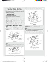
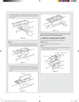
STEP 4 • Place the blower unit into the opening. • Secure the Case Blow Fan Top, the blower motor and cover to the microwave oven with the screws (1, 2 and 3) from Steps 1 and 2. See Figure 15. Figure 15 • Carefully match the exhaust opening location of the microwave and attach the damper to blower motor cover by sliding it into the guides at the blower motor cover. See Figures 16, 17. 8 OVEN INSTALLATION THIS OVEN CANNOT BE PROPERLY INSTALLED WITHOUT REFERRING TO THE MOUNTING INSTRUCTIONS FOUND ON BOTH TEMPLATES. READ AND FOLLOW MOUNTING INFORMATION ON BOTH TOP CABINET AND WALL TEMPLATES. MOUNTING PLATE STEP 1 - SETUP POSITION • Draw a line down the middle of the studs (see Wall Construction, page 3). • Draw a vertical line on the wall at the center of the 30" wide space. See Figure 18. NOTE: Use the wall template for the rear wall. Reference Wall Template prior to proceeding. Installation of this product requires 2 people. Power Supply Cord Hole House Duct C A C CC B Figure 16 Figure 17 Be sure that the damper hinge is on the front and the damper swings free into the wall outlet. Mounting Plate Figure 18 STEP 2 - DRILLING Reference the Wall Template. STEP 3 - TIGHTENING THE SCREWS To attach the mounting plate to the wall using the toggle bolt assemblies and/or lag screws: • Insert toggle bolts through mounting plate at required locations and add the spring loaded toggles. See Figure 19. Be sure you leave space at least the thickness of the wall between the mounting plate and the end of the toggle nut, (in closed position). If you do not leave this space, the toggle nut will not open on the other side of the wall. 1.TINSKB278MRR0_Viking_VMOH330SS_OTR_Install_E,S,F.indd 7 E 7 Figure 19 1/31/19 11:07 AM
-
 1
1 -
 2
2 -
 3
3 -
 4
4 -
 5
5 -
 6
6 -
 7
7 -
 8
8 -
 9
9 -
 10
10 -
 11
11 -
 12
12 -
13
-
14
-
15
-
16
-
17
-
18
-
19
-
20
-
21
-
22
-
23
-
24
-
25
-
26
-
27
-
28
-
29
-
30
-
31
-
32
-
33
-
34
-
35
-
36
 |
 |
