Weider 8530 User Manual - Page 14
Acable Assembly Bseat Assembly
 |
View all Weider 8530 manuals
Add to My Manuals
Save this manual to your list of manuals |
Page 14 highlights
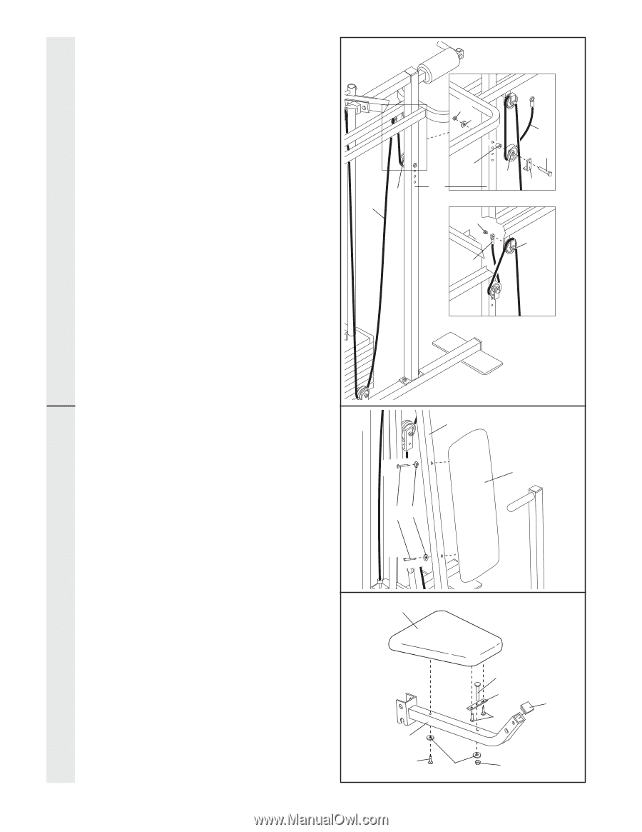
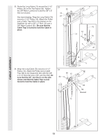
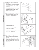
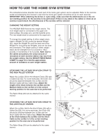
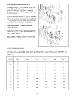
CABLE ASSEMBLY 25. See inset drawing A. Note: The inset drawing shows the view from the other side of the Squat Arm Upright (56). Wrap the Long Cable (72) around a "V"-Pulley (50). Attach the "V"-Pulley and a Long Cable Trap (31) to the top hole in the Squat Arm Upright with the 3/8" x 5" Bolt (67), the 5/8" x 3/8" Spacer (76), a 3/8" Flat Washer (9), and a 3/8" Nylon Locknut (21). Position the Long Cable Trap (31) as shown. See inset drawing B. Note: The inset drawing shows the view from the other side of the Squat Arm Upright (56). Slide the end of the Long Cable (72) onto the end of the 3/8" x 2 1/4" Bolt (94). Thread another 3/8" Jam Nut (92) onto the Bolt. Do not tighten the second Jam Nut. There must be room between the two Jam Nuts for the end of the Cable to pivot. 25 50 72 Insets show view from other side A 21 9 76 56 72 67 50 31 B 92 94 72 SEAT ASSEMBLY 26. Attach the Backrest (41) to the Front Upright 26 (42) with two 1/4" x 2 1/2" Screws (43) and two 1/4" Flat Washers (10). 42 41 43 10 27. Press a 1 1/2" Inner Cap (32) into the Seat Frame (36). 27 13 Insert a 1/4" x 2" Carriage Bolt (38) through the center hole in the Seat Plate (37). Attach the Seat Plate to the Seat (13) with two 1/4" x 3/4" Screws (18). Insert the 1/4" x 2" Carriage Bolt (38) through the indicated hole in the Seat Frame (36). Tighten a 1/4" Nylon Locknut (2) with a 1/4" Flat Washer (10) onto the Carriage Bolt. Attach the other end of the Seat (13) to the Seat Frame (36) with a 1/4" Flat Washer (10) and a 1/4" x 2" Machine Screw (81). 38 37 32 18 36 81 10 2 14
-
 1
1 -
2
-
3
-
4
-
5
-
6
-
7
-
8
-
 9
9 -
 10
10 -
 11
11 -
 12
12 -
 13
13 -
 14
14 -
 15
15 -
 16
16 -
 17
17 -
 18
18 -
 19
19 -
20
-
21
-
22
-
23
-
24
-
25
-
26
-
27
-
28
-
29
-
30
 |
 |