Weider Cjxt3 Master Trainer User Manual - Page 4
Assembly
 |
View all Weider Cjxt3 Master Trainer manuals
Add to My Manuals
Save this manual to your list of manuals |
Page 4 highlights
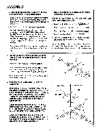
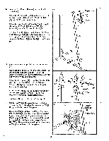
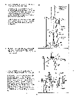
ASSEMBLY Before beginning assembly, carefully read the following information and instructions: • Place all parts of the weight system in a cleared area and remove the packing materials; do not dispose of the packing materials until assembly is completed. • Read each assembly step before you begin. • For help identifying the small parts used in assembly, use the PART IDENTIFICATION CHART located in the center of this manual. Note: Some small parts may have been preattached for shipping purposes. If a part is not in the parts bag, check to see if it has been preattached. • As you assemble the weight system, make sure that all parts are oriented as shown in the drawings. • Tighten all parts as you assemble them, unless instructed to do otherwise. THE FOLLOWING TOOLS (NOT INCLUDED) ARE REQUIRED FOR ASSEMBLY: • Two (2) adjustable wrenches • One (1) standard screwdriver • One (1) phIllips screwdriver • One (1) Rubber Mallet • Lubricant, such as grease or petroleum Jelly, and soapy water will also be needed. Assembly will be more convenient if you have the following tools: A socket set, a set of open-end or closed-end wrenches, or a set of ratchet wrenches. 1. Before you begin, make sure that you have carefully read the instructions at the top of this page. Press a 2" inner Cap (27) into the Base (4). Attach the Pulley Plate (20) to the Base (4) with two 5/16" x 2 3/4" Bolts (11), two 5/16" Flat Washers (8), and two 5/16" Nylon Locknuts (3). Insert the two 5/16" x 2 1/2" Carriage Bolts (1) up through the Base (4). 2. Press the two 2" Outer Caps (88) onto the Stabilizer (5). Insert two 5/16" x 2 3/4" Carriage Bolts (14) up through the Stabilizer (5). Slide the bracket on the end of the Base (4) onto the Carriage Bolts. Slide the Rear Upright (82) onto the Carriage Bolts. Thread two 5/16" Nylon Locknuts (3) onto the Carriage Bolts. Do not tighten the Nylon Locknuts yet. Attach the slotted end of the Brace (86) to the Rear Upright (82) with a 5/16" x 2 3/4" Bolt (11), 5/16" Flat Washer (8) and 5/16" Nylon Locknut (3). Do not tighten the Nylon Locknut yet. Attach the other end of the Brace (86) to the Stabilizer (5) with a 5/16" x 2 3/4" Bolt (11), 5/16" Flat Washer (8), and 5/16" Nylon Locknut (3). Do not tighten the Nylon Locknut yet. 1 20 3 4 27 2 Low Side 11 86-Slot 11 Bracket 82 III 8 88 3 5 88 8 3 4 14 4
-
 1
1 -
 2
2 -
 3
3 -
 4
4 -
 5
5 -
 6
6 -
 7
7 -
 8
8 -
 9
9 -
 10
10 -
11
-
12
-
13
-
14
-
15
-
16
-
17
-
18
-
19
-
20
-
21
-
22
-
23
-
24
-
25
-
26
-
27
 |
 |
