Weider Cjxt3 Master Trainer User Manual - Page 6
lower
 |
View all Weider Cjxt3 Master Trainer manuals
Add to My Manuals
Save this manual to your list of manuals |
Page 6 highlights
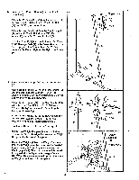
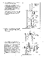
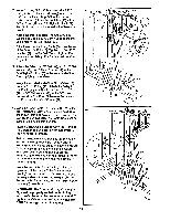
6. Press the Weight Tube Endcap (79) into the indi- 6 cated end of the Weight Tube (80). Insert the Weight Tube (80) into the stack of Weights (25). Slide the tenth Weight (25) onto the upper end of the Weight Tube. The Weight must be turned so the "weidee' logo is on top. The Weight Tube must be turned so the welded pin is in the pin groove in the Weight. Locate the lower ends of the Weight Guides (72) (there are holes near the upper ends). Insert the lower ends of the Weight Guides into the ten Weights (25). 7. Attach the upper ends of the Weight Guides (72) to the Top Frame (67) with the 5/16" x Bolt 7 (7111 them hurl 1 /9" v "31A" CrIne.or. 17'2% nnr1 n Cila" Nylon Locknut (3). Upper Ends of Weight Guides have Holes 72 'Weider Logo on 25 Top Pin Groove 80 Welded Tube 79 25 73 72 3 67 8. Press two 1 3/4" Inner Caps (44) and two 1" Round Inner Caps (49) into the Arm Frame (52). 8 Lubricate the upper axle on the Arm Frame (52). Hold the axle between the two An-n Frame Bushings (68). Set the Arm Frame Bushings and the Arm Frame on the plate welded to the top of the Top Frame (67). The Arm Frame must be turned so the bracket is facing away from the Front Upright (42). Place the Arm Frame Bracket (69) over the Arm Frame Bushings. Attach the Arm Frame Bracket to the Top Frame with four 1/4" x 3/4" Screws (18) and 1/4" Nylon Locknuts (7). 6 74 72 18 69 68 52-Lubricate 49 .67 49 O 7 42 Bracket
-
 1
1 -
 2
2 -
 3
3 -
 4
4 -
 5
5 -
 6
6 -
 7
7 -
 8
8 -
 9
9 -
 10
10 -
 11
11 -
 12
12 -
13
-
14
-
15
-
16
-
17
-
18
-
19
-
20
-
21
-
22
-
23
-
24
-
25
-
26
-
27
 |
 |
