Weider Pro 9735 English Manual - Page 10
Arm Assembly, Frame Assembly - parts
 |
View all Weider Pro 9735 manuals
Add to My Manuals
Save this manual to your list of manuals |
Page 10 highlights
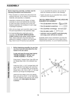
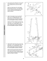
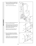
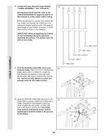
FRAME ASSEMBLY 13. Attach the Leg Press Plate (11) to the Adjustment Tube (10) with a 5/16" x 2 1/2" Bolt (39), two 5/16" Washers (20) and a 5/16" Nylon Locknut (40). Be sure that the Leg Press Plate and Adjustment Tube are oriented as shown. Press a 1 3/4" Square Inner Cap (48) into the Adjustment Tube (10). 13 48 10 20 40 39 Angle 11 14. Attach the Adjustment Tube (10) to the Leg Press Arm (9) with the Small Lock Pin (73). Be sure the Leg Press Plate (11) is oriented as shown. Press two 2" Square Inner Caps (56) into the Leg Press Arm (9). 14 73 9 10 11 56 ARM ASSEMBLY 15. Locate and open the parts bag labeled 15 "ARM ASSEMBLY." Attach the Large Bumper (53) to the Front Seat Frame (8) with the #10 x 1" Tap Screw (100). Lubricate the 3/8" x 3 1/4" Bolt (71). Attach the Leg Press Arm (9) to the Press Base (13) with the Bolt and a 3/8" Nylon Locknut (42). 16. Press a 1" x 7/8" Plastic Bushing (54) onto 16 each welded spacer on the Press Frame (12). Slide the Press Frame onto the Press Base (13) so that the Plastic Bushings are aligned with the indicated tube. Note: This will be a tight fit. Make sure that the higher hole is on the side shown. Lubricate the 3/8" x 8" Bolt (52). Attach the Press Frame (12) to the Press Base (13) with the Bolt and a 3/8" Nylon Locknut (42). 10 8 9 13 53 100 42 71-Lubricate Higher Hole Welded Spacers 42 Tube 12 13 52-Lubricate 54
-
 1
1 -
2
-
3
-
4
-
 5
5 -
 6
6 -
 7
7 -
 8
8 -
 9
9 -
 10
10 -
 11
11 -
 12
12 -
 13
13 -
 14
14 -
 15
15 -
16
-
17
-
18
-
19
-
20
-
21
-
22
-
23
-
24
-
25
-
26
-
27
-
28
-
29
-
30
-
31
-
32
-
33
-
34
-
35
-
36
 |
 |
