Weider Pro 9735 English Manual - Page 19
Large U Bracket. Note: This may come
 |
View all Weider Pro 9735 manuals
Add to My Manuals
Save this manual to your list of manuals |
Page 19 highlights
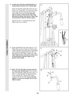
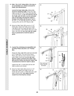
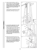
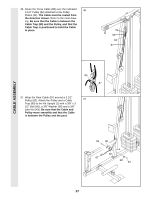
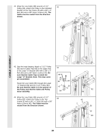
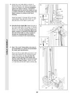
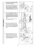
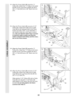
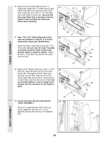
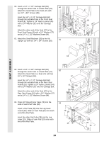
42. Wrap the Low Cable (89) around a 3 1/2" 42 Pulley (82). Attach the Pulley to the indicated bracket on the Top Frame (2) with a 3/8" x 2" Bolt (50) and a 3/8" Nylon Locknut (42). The Cable must be routed from the direction shown. 2 42 50 82 89 CABLE ASSEMBLY 43. See the inset drawing. Attach a 3 1/2" Pulley (82) and a Cable Trap (80) to the upper hole 43 in the Large "U" Bracket (84) with a 3/8" x 2" Bolt (50) and a 3/8" Nylon Locknut (42). Be sure that the Cable Trap is inside the 89 Large "U" Bracket. Note: This may come pre-assembled. 80 82 Route the Low Cable (89) through the Large "U" Bracket (84) and the 3 1/2" Pulley (82). Be sure that the Cable is in the groove of 42 50 the Pulley and that the Cable and Pulley move smoothly. 84 89 82 84 44. Wrap the Low Cable (89) around a 3 1/2" Pulley (82). Attach the Pulley to the Top 44 Frame (2) with a 3/8" x 2" Bolt (50) and a 3/8" Nylon Locknut (42). The Cable must be routed from the direction shown. 42 2 50 82 89 19
-
 1
1 -
2
-
3
-
4
-
5
-
6
-
7
-
8
-
9
-
10
-
11
-
12
-
13
-
 14
14 -
 15
15 -
 16
16 -
 17
17 -
 18
18 -
 19
19 -
 20
20 -
 21
21 -
 22
22 -
 23
23 -
 24
24 -
25
-
26
-
27
-
28
-
29
-
30
-
31
-
32
-
33
-
34
-
35
-
36
 |
 |
