Weider Pro 9735 English Manual - Page 11
Arm Assembly
 |
View all Weider Pro 9735 manuals
Add to My Manuals
Save this manual to your list of manuals |
Page 11 highlights
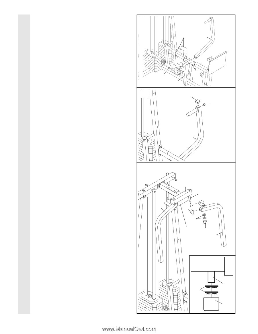
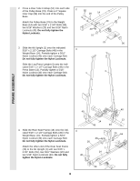
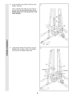
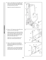
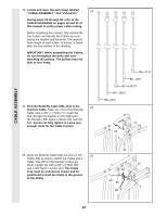
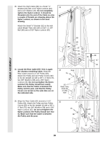
17. Attach a Press Arm (7) to one side of the 17 Press Frame (12) with two 5/16" x 2 1/2" Bolts (39) and two 5/16" Nylon Locknuts (40). Attach the other Press Arm (7) to the Press Frame (12) in the same manner. 39 7 ARM ASSEMBLY 18. Press a 1" Round Inner Cap (70) into one of 18 the Press Arms (7). Press a 1 3/4" Square Inner Cap (48) into the Press Arm. Repeat this step for the other Press Arm (not shown). 40 7 12 48 70 7 19. Lubricate both axles on the Butterfly Frame (3). 19 Refer to the drawing and identify the Right Arm (5) and the Left Arm (6). Press a 1 3/4" Square Inner Cap (48) into the upper end of the Left Arm (6). Slide the Left Arm onto the indicated axle. Note: Be careful 5 not to confuse the Left Arm with the Right Arm (5). Be sure that the upper end of the Left Arm is behind the indicated bracket on the Butterfly Frame (3). IMPORTANT NOTE: Before assembling the 1" Retainers (45) used in this step, be sure that you thoroughly understand the step. The Retainers can be assembled only once. If they must be removed, you will need to order new Retainers. Tap two 1" Retainers (45) and a 1" Round Outer Cap (46) onto the axle. Be sure that the teeth on the Retainers bend toward the Round Outer Cap, as shown in the inset drawing. Attach the Right Arm (5) in the same manner. 11 3 Lubricate Axle 48 45 Bracket 46 6 Axle 45 46
-
 1
1 -
2
-
3
-
4
-
5
-
 6
6 -
 7
7 -
 8
8 -
 9
9 -
 10
10 -
 11
11 -
 12
12 -
 13
13 -
 14
14 -
 15
15 -
 16
16 -
17
-
18
-
19
-
20
-
21
-
22
-
23
-
24
-
25
-
26
-
27
-
28
-
29
-
30
-
31
-
32
-
33
-
34
-
35
-
36
 |
 |