Weider Pro 9735 English Manual - Page 15
of Pulley Plates 31 and 3 1/2 Pulleys - pulley routing
 |
View all Weider Pro 9735 manuals
Add to My Manuals
Save this manual to your list of manuals |
Page 15 highlights
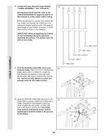
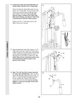
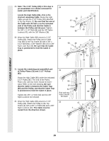
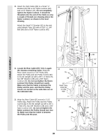
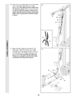
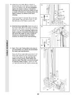
CABLE ASSEMBLY 29. Note: The 3 1/2" Pulley (82) in this step is 29 pre-assembled. It is shown removed for easier part identification. Locate the High Cable (86)-this is the shortest remaining Cable. Route the High Cable around the 3 1/2" Pulley (82) attached to the Top Frame (2). Be sure that the end of the Cable with the ball is on the indicated side of the Pulley and that the Cable is between the Pulley and the post. Tighten the 3/8" x 3 1/2" Bolt (66) and the 3/8" Nylon Locknut (42), with the 3/8" Washer (38). 30. Wrap the High Cable (86) around a 3 1/2" 30 Pulley (82). Attach the Pulley and a Cable Trap (80) to the Top Frame (2) with a 3/8" x 3 1/2" Bolt (66), a 3/8" Washer (38) and a 3/8" Nylon Jam Nut (43). Be sure that the Cable Trap is positioned to hold the Cable in place. 38 42 Post 86 2 82 66 66 38 2 80 82 43 86 31. Locate the remaining pre-assembled pair of Pulley Plates (31) and 3 1/2" Pulleys 31 (82). Route the High Cable (86) under the indicated 3 1/2" Pulley (82). The end of the Pulley Plates (31) with two holes should be downward. Refer to the inset drawing. Be sure that the Cable is between the Cable Trap (80) and the Pulley, and that the Cable Trap is positioned to hold the Cable in place. Tighten the 3/8" x 2" Bolt (50) and the 3/8" Nylon Locknut (not shown). 86 50 31 End with two holes should be down 86 82 80 32. Wrap the High Cable (86) around a 3 1/2" 32 Pulley (82). Attach the Pulley to the Top Frame (2) with a 3/8" x 2" Bolt (50) and a 3/8" Nylon Locknut (42). The Cable must be routed from the direction shown. 42 2 50 82 86 15
-
 1
1 -
2
-
3
-
4
-
5
-
6
-
7
-
8
-
9
-
 10
10 -
 11
11 -
 12
12 -
 13
13 -
 14
14 -
 15
15 -
 16
16 -
 17
17 -
 18
18 -
 19
19 -
 20
20 -
21
-
22
-
23
-
24
-
25
-
26
-
27
-
28
-
29
-
30
-
31
-
32
-
33
-
34
-
35
-
36
 |
 |
